Light is the highest-weightage physics chapter in Class X, contributing 12–15 marks. Mirror formula, lens formula, and power of a lens are mandatory formula questions. Ray diagrams (concave mirror, convex lens, concave lens) are guaranteed 3–5 mark diagram questions in CBSE Boards. NTSE includes sign convention problems and nature/position/size of image MCQs.
Key Concept Highlights
Laws of Reflection
Spherical Mirrors (Concave and Convex)
Key Terms: Focus, Centre of Curvature, Radius, Pole
Sign convention is the make-or-break skill — distances measured opposite to incident light are negative. For mirrors: u is always negative (real object); for concave f is negative. For lenses: f is positive for convex, negative for concave. Memorise all 6 object-position cases for both concave mirror and convex lens. Power in dioptres requires focal length in METRES. Time investment: 6–7 days.
Chapter 9 · CBSE · Class X
🔍
Diffraction of Light
LightReflection of LightRefraction of LightLaws of ReflectionLaws of RefractionSpherical MirrorsConcave MirrorConvex MirrorMirror FormulaMagnificationRefraction through Glass SlabLensesConvex LensConcave LensLens FormulaPower of a LensRefractive IndexImage FormationRay DiagramsNCERT Class X Chapter 9
📘 Definition
Diffraction is the phenomenon in which light waves bend or spread when they pass through a narrow
aperture or around the edges of an obstacle. It is a clear evidence of the wave nature of light.
💡 Concept
When light encounters a slit comparable to its wavelength, it does not travel in straight lines only.
Instead, wavefronts spread out into the region beyond the slit.
This spreading leads to formation of alternate bright and dark regions.
Diffraction becomes significant when aperture size ≈ wavelength of light.
🔢 Formula
Important Formula
For single slit diffraction:
\[ a \sin \theta = n\lambda \]
a = width of slit
\(\lambda\) = wavelength of light
\(\theta\) = angle of diffraction
n = order of minima (n = 1,2,3,...)
📐 Derivation
Derivation (Conceptual)
Consider a slit of width \(a\). According to Huygens’ principle, every point on the slit acts as a
secondary source of wavelets.
Divide slit into two equal halves.
Light from corresponding points cancels due to destructive interference.
This condition leads to first minimum when:
\[ a \sin \theta = \lambda \]
Similarly, higher order minima occur at:
\[ a \sin \theta = n\lambda \]
🎨 SVG Diagram
Diffraction of Light through a Narrow Slit
✏️ Example
Why is diffraction not observed in everyday life easily?
Diffraction is significant only when obstacle size ≈ wavelength.
Compare wavelength of visible light (~10⁻⁷ m) with daily objects.
Since most objects are much larger than wavelength, diffraction is negligible.
What happens when slit width decreases?
Diffraction increases, spreading becomes more pronounced.
⚡ Exam Tip
Always mention "wave nature of light" in theory answers.
Use correct condition: \( a \sin \theta = n\lambda \)
Write "diffraction increases as slit width decreases".
Draw neat labeled diagram for full marks.
❌ Common Mistakes
Confusing diffraction with refraction.
Writing wrong condition (using interference formula incorrectly).
Ignoring wavelength dependence.
📋 Case Study
A beam of monochromatic light passes through a narrow slit and spreads out. A student observes that
decreasing slit width increases spreading.
Question: Explain the reason scientifically.
Answer: As slit width becomes comparable to wavelength, diffraction increases due to stronger
wave interference effects.
🌟 Importance
Frequently asked 2–3 mark conceptual question.
Linked with wave optics (foundation for higher classes).
Important for understanding limitations of optical instruments.
🎬 Visualisation
diffraction of a light ray passing through a slit
Animation showing diffraction of a light ray passing through a slit
🔍
Reflection of Light
📘 Definition
Reflection of light is the phenomenon in which light rays strike a surface and bounce back into the
same medium without any change in wavelength.
🪞 Laws Of Reflection
The incident ray, reflected ray and normal lie in the same plane.
Angle of incidence equals angle of reflection:
\[ i = r \]
🎨 SVG Diagram
🗂️ Types / Category
Types of Reflection
Regular Reflection
Occurs when light reflects off a smooth, polished surface such as a plane mirror, where all reflected rays are parallel to each other. This produces a clear and well‑defined image, like the sharp reflection you see in a glass mirror or calm water surface.
Diffuse Reflection
Occurs when light reflects off a rough or uneven surface, causing the reflected rays to scatter in many directions. This is why we see non‑shiny surfaces clearly from different angles, such as paper, walls, or a waxy leaf, even though they do not form a clear mirror image.
✏️ Example
A ray strikes a mirror at 30°. Find angle of reflection.
Using law, \[ r = i = 30^\circ \]
⚡ Exam Tip
Always draw normal before solving numericals.
Clearly label angles in diagrams.
Write both laws for full marks.
🔍
Spherical Mirrors
📘 Definition
A spherical mirror is a mirror whose reflecting surface forms part of a hollow sphere.
🗂️ Types / Category
Types of spherical mirror
Concave Mirror
A spherical mirror that bulges inward (curved surface facing the source of light); it converges parallel incident light rays towards a focal point in front of the mirror. Common examples include shaving mirrors, dentist’s head mirrors, and the reflecting mirrors used in Newtonian telescopes and solar concentrators.
Convex Mirror
A spherical mirror that bulges outward (curved surface facing away from the source of light); it diverges parallel incident light rays, forming a virtual, diminished, and erect image behind the mirror. Typical examples are the rear‑view mirrors in vehicles and security mirrors used in shops or at blind corners for a wider field of view.
🔢 Formula
Important Relations
Relation Between Radius of Curvature \('R\;'\) and focal length \('f\;'\)
\[ f = \frac{R}{2} \]
Mirror Formula
\[ \frac{1}{f} = \frac{1}{v} + \frac{1}{u} \]
Magnification
\[ m = \frac{h_i}{h_o} = \frac{-v}{u} \]
📌 Note
Sign Convention (Cartesian)
All distances measured from pole
Left side = negative
Right side = positive
Upward height = positive
Downward height = negative
📐 Derivation
Derivation of Mirror Formula
Consider a spherical mirror of small aperture. Let an object AB be placed on the principal axis, and let its image A′B′ be formed after reflection.
Using the geometry of the ray diagram, two pairs of triangles are obtained that are similar.
From the similar triangles formed near the pole of the mirror, we get a relation between the height of the object, the height of the image, and their distances from the pole:
\[
\frac{A'B'}{AB} = -\frac{v}{u}
\]
By applying the second pair of similar triangles involving the focus F, we obtain another relation:
\[
\frac{A'B'}{AB} = -\frac{f-v}{f}
\]
Equating the two expressions,
\[
-\frac{v}{u} = -\frac{f-v}{f}
\]
On simplifying,
\[
\frac{f-v}{f} = \frac{v}{u}
\]
\[
u(f-v)=fv
\]
\[
uf-uv=fv
\]
\[
uf=fv+uv
\]
Dividing the whole equation by ufv, we get
\[
\frac{1}{v}+\frac{1}{u}=\frac{1}{f}
\]
Thus, the mirror formula is
\[
\boxed{\frac{1}{f}=\frac{1}{v}+\frac{1}{u}}
\]
This relation holds for spherical mirrors when distances are measured according to the New Cartesian sign convention.
✏️ Example
Numerical Example
Object at 20 cm from concave mirror, f = -10 cm. Find image distance.
A student places an object between F and P of a concave mirror.
Question: Describe the image formed.
Answer: Image is virtual, erect, and magnified behind the mirror.
🔍
Ray Diagrams for Image Formation by Spherical Mirrors
📘 Definition
Ray diagrams are graphical representations used to trace the path of light rays reflected from mirrors
to determine the position, size, and nature of the image formed.
🌟 Importance
Why Ray Diagrams Matter
Essential for 3–5 mark CBSE questions.
Helps visualize real vs virtual images.
Forms the basis of mirror formula derivation.
📌 Note
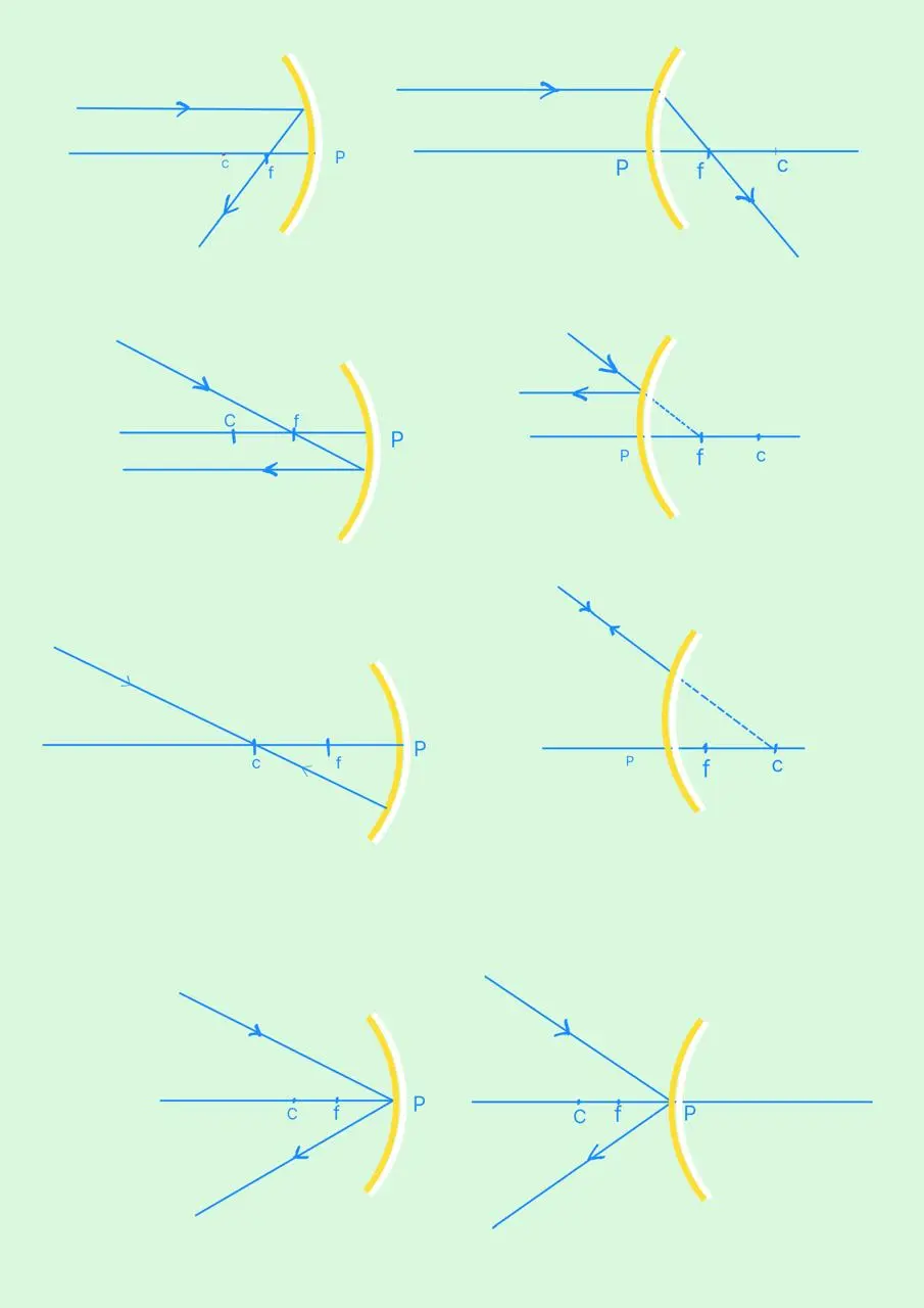
Standard Rays Used in Construction
Parallel Ray: A ray parallel to the principal axis passes through the focus after reflection from a concave mirror, and appears to come from the focus after reflection from a convex mirror.
Focus Ray: A ray passing through the focus reflects parallel to the principal axis.
Centre Ray: A ray passing through the centre of curvature retraces its path after reflection.
Pole Ray: A ray incident at the pole reflects according to the law of reflection, with \( i = r \).
🎨 SVG Diagram
Stepwise Construction (Concave Mirror)<
The reflected rays meet in front of the mirror to form a real, inverted image.
Draw the principal axis and the concave mirror.
Mark the pole \(P\), focus \(F\), and centre of curvature \(C\).
Draw one ray parallel to the principal axis; after reflection, it passes through the focus.
Draw a second ray through the focus; after reflection, it becomes parallel to the principal axis.
The intersection of the reflected rays gives the image position.
📌 Note
Convex Mirror Insight
Reflected rays diverge.
Image formed by extending rays backward.
Always virtual, erect, diminished.
💡 Concept
Conceptual Clarity
Real image → rays actually meet.
Virtual image → rays appear to meet.
Minimum two rays required for accuracy.
🔢 Formula
Connection with Mirror Formula
Ray diagrams lead to formation of similar triangles, which give:
\[ \frac{1}{f} = \frac{1}{v} + \frac{1}{u} \]
✏️ Example
Object placed beyond C in concave mirror. Where is image formed?
Use parallel ray + focus ray
Image forms between F and C, real and inverted.
⚡ Exam Tip
Always draw arrows on rays.
Label F, C, P clearly.
Use two rays minimum.
Keep diagram neat and proportional.
❌ Common Mistakes
Using incorrect ray rules.
Forgetting backward extension in convex mirror.
Not marking principal axis.
Drawing more than necessary rays (wastes time).
📋 Case Study
A student draws only one ray while constructing a ray diagram.
Question: Why is the diagram incorrect?
Answer: At least two rays are needed to determine exact image position.
🔍
Sign Convention for Reflection by Spherical Mirrors
📘 Definition
The New Cartesian Sign Convention is a standardized method of assigning positive and negative signs to
distances, heights, and focal lengths in mirror problems, ensuring consistent application of formulas.
🎨 SVG Diagram
Coordinate System Representation
New Cartesian coordinate system for mirrors
Rules
Object is always placed on the left side of the mirror.
All distances are measured from the pole (P).
Distances to the right (+x direction) are positive.
Distances to the left (−x direction) are negative.
Heights above principal axis (+y) are positive.
Heights below principal axis (−y) are negative.
📊 Comparison Table
Quick Sign Reference Table
Quick Sign Reference Table
Quantity
Concave Mirror
Convex Mirror
Focal length (f)
Negative
Positive
Radius (R)
Negative
Positive
Object distance (u)
Always Negative
Always Negative
Image distance (v)
Negative (real), Positive (virtual)
Always Positive
Image height (hᵢ)
Negative (inverted), Positive (erect)
Positive
🔢 Formula
\[ \frac{1}{f} = \frac{1}{v} + \frac{1}{u} \]
\[ m = \frac{-v}{u} \]
✏️ Example
🗒️
Quetion
Object at 15 cm in front of concave mirror, f = 10 cm. Find image distance.
Image is real and formed in front of mirror 30 cm distant
💡 Concept
Conceptual Insight
Signs indicate direction, not magnitude.
Negative image distance → real image.
Positive image distance → virtual image.
⚡ Exam Tip
Always write sign values before solving.
Never assume sign—derive from diagram.
Check final sign to interpret nature of image.
❌ Common Mistakes
Taking focal length of concave mirror as positive.
Ignoring negative sign of object distance.
Mixing lens and mirror sign conventions.
📋 Case Study
A student gets a positive image distance for a concave mirror in a numerical.
Question: What does this indicate?
Answer: Image is virtual and formed behind the mirror.
🔍
Mirror Formula and Magnification (Derivation, Numericals & Concepts)
📘 Definition
The mirror formula establishes a mathematical relationship between the object distance (u),
image distance (v), and focal length (f) of a spherical mirror.
\[ \frac{1}{f} = \frac{1}{v} + \frac{1}{u} \]
f → focal length of mirror
v → image distance
u → object distance
Magnification
Magnification describes how much larger or smaller the image is compared to the object.
\[ m = \frac{h_i}{h_o} = \frac{-v}{u} \]
\( m > 1 \) → image enlarged
\( 0 < m < 1 \) → image diminished
\( m < 0 \) → image inverted (real)
\( m > 0 \) → image erect (virtual)
📐 Derivation
Derivation of Mirror Formula
Derivation of Mirror Formula
The mirror formula is derived using similar triangles formed in ray diagrams:
Consider object AB and image A'B'.
Using geometry of triangles:
\[
\frac{A'B'}{AB} = \frac{v}{u}
\]
Using another pair of similar triangles involving focus:
\[
\frac{A'B'}{AB} = \frac{f - v}{f}
\]
Equating and simplifying leads to:
\[ \frac{1}{f} = \frac{1}{v} + \frac{1}{u} \]
Conceptual Diagram
Geometry for derivation of 1/f = 1/v + 1/u
✏️ Example
Numerical Example
An object is placed 20 cm in front of a concave mirror of focal length 15 cm.
Find image position and magnification.
Negative \( v \) → image is real (in front of mirror)
Negative \( h_i \) → image is inverted
\( |m| = 1 \) → image is same size
Object is at centre of curvature (C = 2f)
💡 Concept
Concept Link
When an object is placed at the centre of curvature of a concave mirror, the image is formed at the same
position, real, inverted, and of the same size.
⚡ Exam Tip
Always keep sign of height in final answer
\( m = -1 \) is a standard result → remember it
Link answer with ray diagram concept for full marks
❌ Common Mistakes
Writing \( h' = +4 \, cm \) instead of \( -4 \, cm \)
Ignoring sign of magnification
Not identifying centre of curvature case
🔍
Example-6
❓ Question
A concave mirror forms a virtual image twice the size of the object when the object is placed 5 cm from it. Find:
Refractive index is a measure of how much light slows down in a medium compared to another medium.
It determines the bending of light during refraction.
Relation with Snell’s Law
\[
n_{21} = \frac{\sin i}{\sin r}
\]
This gives refractive index of medium 2 with respect to medium 1.
Relative Refractive Index
\[
n_{21} = \frac{v_1}{v_2}
\]
\( v_1 \) = speed of light in medium 1
\( v_2 \) = speed of light in medium 2
Similarly:
\[
n_{12} = \frac{v_2}{v_1}
\]
🗒️
Important
\[
n_{12} = \frac{1}{n_{21}}
\]
📌 Note
Absolute Refractive Index
When refractive index is measured with respect to vacuum (or air), it is called absolute refractive index.
\[
n = \frac{c}{v}
\]
\( c = 3 \times 10^8 \, m/s \) (speed of light in vacuum)
\( v \) = speed of light in medium
👁️ Observation
Optical Density & Refractive Index
Higher refractive index → optically denser medium
Lower refractive index → optically rarer medium
Denser medium slows light more
📊 Comparison Table
Common Refractive Indices
Medium
Refractive Index
Air
~1.0003
Water
1.33
Glass
1.5
Diamond
2.42
✏️ Example
Speed of light in a medium is \( 2 \times 10^8 \, m/s \). Find refractive index.
Always mention whether index is relative or absolute
Use correct formula based on question
Remember \( n = c/v \) is most commonly asked
❌ Common Mistakes
Confusing relative and absolute refractive index
Writing \( n = v/c \) (wrong)
Ignoring units in speed-based questions
🔍
Optical Density (Concept, Relation & Applications)
📘 Definition
Optical density is a measure of how much a medium slows down light and hence causes refraction.
It is directly related to the refractive index of the medium.
🗒️ Important Clarification
Important Clarification
Optical density is not related to mass density
A medium can be optically denser but physically lighter
It depends on interaction of light with medium, not mass
📌 Note
Relation with Refractive Index
\[
n = \frac{c}{v}
\]
Higher \( n \) → higher optical density
Lower \( n \) → lower optical density
📊 Comparison Table
Comparison of Media
Comparison of Media
Property
Optically Denser Medium
Optically Rarer Medium
Refractive Index
Higher
Lower
Speed of Light
Lower
Higher
Refraction
Towards normal
Away from normal
💡 Concept
Conceptual Understanding
Light bends because its speed changes across media
Greater slowing → greater bending → higher optical density
✏️ Example
Between water (n = 1.33) and glass (n = 1.5), which is optically denser?
Glass is optically denser because it has higher refractive index.
⚡ Exam Tip
Always compare using refractive index
Use correct terms: “optically denser/rarer”
Link with bending direction in answers
❌ Common Mistakes
Confusing optical density with mass density
Assuming heavier object is optically denser
Ignoring relation with refractive index
🔍
Refraction by Spherical Lenses
📘 Definition
A spherical lens is a transparent refracting medium bounded by two spherical surfaces (or one spherical
and one plane surface), which bends light by refraction.
🗂️ Types / Category
Types of Lenses
Convex Lens (Converging)
Thicker at the centre and thinner at the edges; it converges parallel rays to a principal focus. It can form real and inverted images or virtual and enlarged images depending on the object position.
Concave Lens (Diverging)
Thinner at the centre and thicker at the edges; it diverges parallel rays outward as if they came from a principal focus. It always forms a virtual, erect, and diminished image.
🎨 SVG Diagram
Basic Structure
Pure lens profiles: Converging (Thick middle) vs Diverging (Thin middle).
🧠 Remember
Important Terms
Principal Axis: Line joining centres of curvature
Optical Centre (O): Point where ray passes undeviated
Principal Focus (F): Point where parallel rays meet (convex) or appear to diverge (concave)
Focal Length (f): Distance between O and F
🗒️ Important
Ray Rules
Ray parallel to principal axis → passes through focus (convex) or appears from focus (concave)
Ray through focus → emerges parallel to axis
Ray through optical centre → undeviated
🔢 Formula
Lens Formula
\[ \frac{1}{f} = \frac{1}{v} - \frac{1}{u} \]
🔢 Formula
Magnification
\[ m = \frac{h_i}{h_o} = \frac{v}{u} \]
📌 Note
Sign Convention
Distances measured from optical centre
Left side → negative, Right side → positive
Convex lens → \( f > 0 \)
Concave lens → \( f < 0 \)
✏️ Example
Object at 20 cm, convex lens \( f = 10 \, cm \). Find image distance.
Image Formation by Lenses (Ray Diagrams + Formula + Analysis)
📘 Definition
Image formation by lenses occurs due to refraction of light rays, where the position, size, and nature
of the image depend on object distance and type of lens.
🗒️ Standard Rays for Construction
Standard Rays for Construction
Ray parallel to principal axis → passes through focus (convex) or appears from focus (concave)
Ray through focus → emerges parallel to axis
Ray through optical centre → undeviated
🎨 SVG Diagram
Ray Diagram (Convex Lens)
Real, Inverted Image formed by Convex Lens
📊 Comparison Table
Convex Lens (Converging)
Object Position
Image Position
Size
Nature
At infinity
At F₂
Highly diminished
Real, inverted
Beyond 2F₁
Between F₂ & 2F₂
Diminished
Real, inverted
At 2F₁
At 2F₂
Same size
Real, inverted
Between F₁ & 2F₁
Beyond 2F₂
Magnified
Real, inverted
Between F₁ & O
Same side
Magnified
Virtual, erect
📊 Comparison Table
Concave Lens (Diverging)
Object Position
Image Position
Size
Nature
At infinity
At F₁
Highly diminished
Virtual, erect
Anywhere
Between F₁ & O
Diminished
Virtual, erect
🔢 Formula
Lens Formula & Magnification
\[\frac{1}{f} = \frac{1}{v} - \frac{1}{u}\]
\[m = \frac{v}{u}\]
💡 Concept
Conceptual Insights
Convex lens → real or virtual depending on object position
Concave lens → always virtual and diminished
Real images → inverted, Virtual images → erect
✏️ Example
Numerical Example
Object at 15 cm from convex lens, \( f = 10 \, cm \). Fid distance of Image
Image Formation in Lenses Using Ray Diagrams (Stepwise Construction)
📘 Definition
Ray diagrams are graphical methods used to determine the position, size, and nature of images formed by
lenses by tracing the path of refracted light rays.
🌟 Importance
Essential for 3–5 mark CBSE questions
Helps visualize real vs virtual images
Forms the basis of lens formula derivation
📌 Note
Ray Rule
Parallel Ray: After refraction, passes through focus (convex) or appears from focus (concave).
Ray through Focus: Emerges parallel to principal axis.
Ray through Optical Centre: Passes undeviated.
🎨 SVG Diagram
Ray Diagram (Convex Lens)
CONVEX CONVERGENCE
Step by step Construction
Draw principal axis and lens.
Mark optical centre (O) and focal points (F₁, F₂).
Place object at given position
Draw any two standard rays.
Locate intersection of refracted rays → image position.
If rays diverge, extend them backward to locate virtual image.
A student obtains negative image distance for convex lens.
Question: What does it indicate?
Answer: Image is virtual and formed on same side as object.
🔍
Lens Formula and Magnification (Derivation, Numericals & Concepts)
📘 Definition
The lens formula gives the relationship between object distance (u), image distance (v), and focal
length (f) of a spherical lens.
\[
\frac{1}{f} = \frac{1}{v} - \frac{1}{u}
\]
f → focal length
v → image distance
u → object distance
Magnification
Magnification tells how much the image is enlarged or diminished compared to the object.
\[
m = \frac{h_i}{h_o} = \frac{v}{u}
\]
\( m > 1 \) → enlarged image
\( 0 < m < 1 \) → diminished image
\( m > 0 \) → erect image
\( m < 0 \) → inverted image
📐 Derivation
Derivation of Lens Formula
GEOMETRIC OPTICS: LENS FORMULA DERIVATION
Derivation of Lens Formula
Using ray‑diagram geometry and similar triangles formed by the object, image, and focal points, we can derive the lens formula.
Consider a real object $AB$ and its real image $A'B'$ formed by a convex lens, with heights $h_o$ and $h_i$ respectively, object distance $u$, image distance $v$, and focal length $f$.
From similar triangles $\triangle ABO \sim \triangle A'B'O$ (ray through the optical center):
$$\frac{h_i}{h_o} = -\frac{v}{u}$$
From similar triangles $\triangle ODF \sim \triangle A'B'F$ (ray parallel to the principal axis passing through the focal point, where $OD = h_o$):
$$\frac{h_i}{h_o} = \frac{v - f}{f}$$
Equating the two expressions for $\frac{h_i}{h_o}$ yields:
$$-\frac{v}{u} = \frac{v - f}{f}$$
\( \text{Image is real, inverted, and magnified.} \)
💡 Concept
Conceptual Insights
Convex lens can form both real and virtual images
Concave lens always forms virtual images
Magnification sign gives orientation directly
📌 Note
Quick Problem-Solving Strategy
Draw rough ray diagram mentally
Apply sign convention
Use lens formula
Verify using magnification
⚡ Exam Tip
Do not confuse lens and mirror formulas
Always assign signs before substitution
State nature of image in final answer
❌ Common Mistakes
Using wrong formula sign
Ignoring negative value of u
Not interpreting magnification
📋 Case Study
A student gets positive magnification for convex lens.
Question: What does it indicate?
Answer: Image is virtual and erect.
🔍
Power of a Lens (Formula, Unit, Combination & Numericals)
📘 Definition
The power of a lens indicates its ability to converge or diverge light. A lens with greater power
bends light more strongly.
🔢 Formula
\[
P = \frac{1}{f}
\]
\( P \) = power of lens (dioptre, D)
\( f \) = focal length (in metres)
Unit of Power
SI unit: dioptre (D)
\( 1 \, D = 1 \, m^{-1} \)
Always convert focal length into metres before calculation
Sign Convention
Convex lens → \( f > 0 \) → \( P > 0 \)
Concave lens → \( f < 0 \) → \( P < 0 \)
Important Conversion
If focal length is given in cm:
\[
P = \frac{100}{f(\text{in cm})}
\]
📌 Note
Combination of Lenses
When lenses are placed in contact:
\[
P_{total} = P_1 + P_2 + P_3 + \dots
\]
Total power is algebraic sum
Useful in spectacles and optical instruments
✏️ Example
1
Example
Find power of lens of focal length 50 cm.
\[
f = 50 \, \mathrm{cm} = 0.5 \, \mathrm{m}
\]
\[
P = \frac{1}{0.5} = 2 \, \mathrm{D}
\]
2
Example
Two lenses of powers +2 D and −1 D are combined. Find total power.
\[P = 2 + (-1) = 1 \, \mathrm{D}\]
💡 Concept
Conceptual Insights
Higher power → smaller focal length
Power and focal length are inversely related
Positive power → converging lens
Negative power → diverging lens
🤔 Did You Know?
Quick Shortcuts
25 cm → 4 D
50 cm → 2 D
100 cm → 1 D
🛠️ Application
Used in spectacles to correct vision defects
Used in cameras and microscopes
⚡ Exam Tip
Always convert cm → m
Check sign of focal length before calculating
Use correct unit (dioptre)
❌ Common Mistakes
Not converting cm to metres
Wrong sign of focal length
Forgetting unit (D)
📋 Case Study
A lens has power −2 D. Identify the type of lens and its focal length.
Answer: Concave lens, \( f = -0.5 \, m \)
🔍
Example-7
❓ Question
A convex lens of focal length 10 cm is placed at a distance of 12 cm from a wall. At what distance from the lens should an object be placed so that a real image is formed on the wall?
🗺️ Roadmap
Solution Roadmap
Apply lens formula
Substitute values with correct signs
Solve for \( u \)
🧩 Solution
Given
Focal length \( f = +10 \, cm \)
Image distance \( v = +12 \, cm \) (real image on wall)
Positive \( v \) → image formed on right side (real image)
Negative \( h_i \) → image is inverted
\( |m| = 2 \) → image is magnified (twice the size)
Image is formed beyond 2F
💡 Concept
Concept Link
When an object is placed between F and 2F of a convex lens, the image is formed beyond 2F,
real, inverted, and magnified.
⚡ Exam Tip
Never drop the negative sign in height
Sign of magnification directly tells orientation
Always state nature (real/virtual, erect/inverted)
❌ Common Mistakes
Writing \( h_i = +14 \, cm \) instead of \( -14 \, cm \)
Ignoring sign of magnification
Not interpreting final result
🔍
Example-9
❓ Question
An object 2 cm tall is placed on the principal axis of a convex (converging) lens of focal length 8 cm. Find the position, nature, and size of the image when the object is
Convex lens → \( f > 0 \), Concave lens → \( f < 0 \)
📍 Key Point
High-Yield Exam Points
Concave lens always forms virtual, erect image
Convex mirror always forms virtual, erect image
Magnifying glass → object within focal length
Real image can be obtained on screen; virtual cannot
NCERT Class X · Chapter 9 · Physics
Light — Reflection & Refraction
A comprehensive AI-powered learning engine with interactive solvers, concept builders, and practice questions
📚 Core Concepts
Organised by sub-topic. Click any concept card to expand.
Reflection of Light
Nature of Light & Reflection Laws
▼
Light travels in straight lines (rectilinear propagation). When light hits a smooth, polished surface it bounces back — this is reflection.
⚡
Laws of Reflection: ① The angle of incidence (∠i) equals the angle of reflection (∠r). ② The incident ray, reflected ray, and the normal at the point of incidence all lie in the same plane.
These laws hold for all types of reflecting surfaces — plane, concave, and convex.
∠i = ∠rAngle of incidence = Angle of reflection
Spherical Mirrors — Concave & Convex
▼
Spherical mirrors are parts of a hollow sphere with a reflecting surface inside (concave) or outside (convex).
Feature
Concave Mirror
Convex Mirror
Also called
Converging mirror
Diverging mirror
Reflecting surface
Inner (curved inward)
Outer (curved outward)
Focal point
Real, in front of mirror
Virtual, behind mirror
Image of distant object
Real, inverted, at F
Virtual, erect, diminished
Common uses
Shaving mirror, dentist's, headlights
Rear-view mirrors, security mirrors
🔑
Key Terms:Pole (P) — centre of mirror surface. Centre of Curvature (C) — centre of the sphere. Radius of Curvature (R) — radius of the sphere. Principal Axis — line through P and C. Principal Focus (F) — point where rays parallel to principal axis converge (concave) or appear to diverge from (convex).
f = R / 2Focal length = Half of radius of curvature
Image Formation by Concave Mirror (All Cases)
▼
Object Position
Image Position
Nature & Size
At infinity
At F
Real, inverted, highly diminished
Beyond C
Between F and C
Real, inverted, diminished
At C
At C
Real, inverted, same size
Between C and F
Beyond C
Real, inverted, magnified
At F
At infinity
Real, inverted, highly magnified
Between F and P
Behind mirror
Virtual, erect, magnified
Mirror Formula & Magnification
▼
1/v + 1/u = 1/fMirror Formula | v = image distance, u = object distance, f = focal length
📐
Sign Convention (New Cartesian): All distances measured from pole P. Distances along the direction of incident light → positive. Against incident light → negative. Heights above principal axis → positive. Below → negative.
m = hₙ / hₒ = −v / uMagnification | h' = image height, h = object height
Interpreting magnification:
✔
m > 0 (positive): image is virtual and erect
✔
m < 0 (negative): image is real and inverted
✔
|m| > 1: image is magnified (larger than object)
✔
|m| < 1: image is diminished (smaller than object)
Refraction of Light
What is Refraction? Laws of Refraction
▼
When light passes from one transparent medium to another, it changes its direction of travel. This bending is called refraction and happens because light travels at different speeds in different media.
⚡
Laws of Refraction (Snell's Law): ① The incident ray, refracted ray, and normal lie in the same plane. ② sin(i) / sin(r) = constant (for a given pair of media and colour of light).
n₁ · sin(i) = n₂ · sin(r)Snell's Law | n₁, n₂ = refractive indices; i = angle of incidence; r = angle of refraction
When light goes denser → rarer medium: it bends away from normal (r > i). When light goes rarer → denser medium: it bends toward normal (r < i).
Refractive Index — Absolute & Relative
▼
n = c / vAbsolute refractive index | c = speed of light in vacuum ≈ 3 × 10⁸ m/s, v = speed in medium
ₙ₁n₂ = n₂ / n₁ = sin(i) / sin(r)Relative refractive index of medium 2 with respect to medium 1
Medium
Refractive Index (approx.)
Vacuum / Air
1.00
Water
1.33
Crown Glass
1.52
Dense Glass
1.65
Diamond
2.42
A higher refractive index means the medium is optically denser and light travels slower in it.
Refraction Through a Glass Slab
▼
When light passes through a rectangular glass slab, it refracts at both surfaces. The emergent ray is parallel to the incident ray but laterally displaced (shifted sideways).
💡
Key fact: At the first surface, light bends toward the normal. At the second surface (emerging from denser to rarer), it bends away from the normal by the same angle. So the net deviation is zero but there's a lateral shift that depends on the thickness of the slab and the angle of incidence.
Spherical Lenses — Convex & Concave
▼
A lens is a transparent optical element bounded by two curved (or one curved, one plane) surfaces.
Feature
Convex (Converging) Lens
Concave (Diverging) Lens
Centre
Thicker at centre
Thinner at centre
Effect on rays
Converges parallel rays to F
Diverges rays; appear from virtual F
Focal length
Positive (+)
Negative (−)
Power
Positive
Negative
Uses
Reading glasses, camera, magnifier
Myopia correction
🔑
Key Terms for Lenses:Optical Centre (O) — centre of lens. Principal Focus (F) — convex lens has real F on both sides; concave has virtual F. Focal Length (f) — distance O to F. Every lens has two foci (F₁ and F₂).
Image Formation by Convex Lens (All Cases)
▼
Object Position
Image Position
Nature & Size
At infinity
At F₂
Real, inverted, highly diminished
Beyond 2F₁
Between F₂ and 2F₂
Real, inverted, diminished
At 2F₁
At 2F₂
Real, inverted, same size
Between F₁ and 2F₁
Beyond 2F₂
Real, inverted, magnified
At F₁
At infinity
Real, inverted, highly magnified
Between O and F₁
Same side as object
Virtual, erect, magnified
For a concave lens, image is always virtual, erect, and diminished, regardless of object position.
Lens Formula, Magnification & Power
▼
1/v − 1/u = 1/fLens Formula | Same sign convention as mirrors (from optical centre)
m = hₙ / hₒ = v / uMagnification for lenses (note: no negative sign unlike mirrors)
P = 1 / f (in metres) | Unit: Dioptre (D)Power of a lens | f must be in metres
➕
Combination of lenses: When lenses are placed in contact, total power = P₁ + P₂ + P₃ + … and effective focal length: 1/f = 1/f₁ + 1/f₂.
⚗️ All Formulas at a Glance
Every formula from Chapter 9 with variables explained and conditions noted.
Mirrors
Mirror Formula
1/f = 1/v + 1/uf = focal length | v = image distance from pole | u = object distance from pole⚠ All distances measured from pole P with sign convention.
Relationship: Focal Length & Radius
f = R / 2 ⟺ R = 2f
Linear Magnification (Mirrors)
m = hₙ / hₒ = −v / uh' = height of image | h = height of object
Concave Mirror
f is negative. u is always negative. v is negative for real image, positive for virtual image.
Convex Mirror
f is positive. u is always negative. v is always positive (virtual image always).
Refraction & Refractive Index
Snell's Law
n₁ · sin(θ₁) = n₂ · sin(θ₂)n₁, n₂ = refractive indices of medium 1 & 2 | θ₁ = angle of incidence | θ₂ = angle of refraction
Absolute Refractive Index
n = c / v = (speed of light in vacuum) / (speed in medium)c = 3 × 10⁸ m/s | n is always ≥ 1 for a physical medium
Relative Refractive Index
₁n₂ = n₂ / n₁ = v₁ / v₂ = sin(i) / sin(r)
Lenses
Lens Formula
1/v − 1/u = 1/fNote the minus sign (−1/u) — different from mirror formula!
Magnification (Lenses)
m = hₙ / hₒ = v / uNo negative sign here — unlike mirrors
Power of a Lens
P = 1 / f(m) [Unit: Dioptre, D]Convert focal length to metres before applying. Convex: P > 0. Concave: P < 0.
f is positive. u negative (object on left). v positive = real image (right side); v negative = virtual image (left side).
Concave Lens
f is negative. Image always virtual, erect, diminished. v always negative (same side as object).
📐 Sign Convention — Quick Reference
For Mirrors
−ve u (object always in front)
−ve f for concave mirror
+ve f for convex mirror
−ve v for real image (in front)
+ve v for virtual image (behind)
For Lenses
−ve u (object always on left)
+ve f for convex lens
−ve f for concave lens
+ve v for real image (right side)
−ve v for virtual image (left side)
🧮 Step-by-Step AI Solver
Enter known values for Mirror, Lens, or Refraction problems. The engine solves and explains every step.
🪞 Mirror Solver
Enter any two of the three values. Leave one blank to solve for it.
🔍 Lens Solver
Enter any two of the three values. The engine will solve and explain each step.
🌊 Snell's Law Solver
Solve for angle of refraction or refractive index. Enter three known values.
⚡ Power & Combination Solver
Enter focal lengths of up to 3 lenses (in cm) to find combined power and effective focal length.
📝 Concept-Building Questions
Original questions with full step-by-step solutions, organised by concept. Not replicated from textbook.
🎯 Knowledge Quiz
Test your conceptual understanding. Feedback and explanation after each answer.
0
Score
0
Answered
—
Total
0% complete
🔬 Interactive Modules
Visual, hands-on learning tools — ray diagrams, refraction visualiser, and more.
🪞 Concave Mirror — Live Ray Diagram
Drag the object slider to change its position. See how the image changes in real time.
Object Distance:35 cm
Focal Length:20 cm
💧 Snell's Law — Refraction Visualiser
Adjust angle of incidence and refractive indices to see how light bends at the interface.
Angle of incidence (°):45°
n₁ (top):1.00
n₂ (bottom):1.50
—
Angle of Incidence
—
Angle of Refraction
—
n₁ (medium 1)
—
n₂ (medium 2)
🔭 Convex Lens — Image Simulator
Move the object to see image position, nature, and magnification dynamically.
Object Distance:40 cm
Focal Length:20 cm
🌈 Refractive Index Explorer
Click a medium to compare its optical properties. Explore how speed and index relate.
💡 Tips, Tricks & Common Mistakes
Curated from common student errors and exam patterns. Study these before your exam.
✨ Tricks & Study Tips
🎯
Mirror vs Lens Formula Memory Trick: Mirror → 1/v + 1/u = 1/f (both positive sides, add). Lens → 1/v − 1/u = 1/f (subtract u side). The minus in lens formula trips students up most often.
🌊
Denser means slower, slower means bends toward normal: When light enters a denser medium (higher n), it slows down and bends toward the normal. Rarer → faster → bends away. Visualise it as a car wheel hitting mud — the wheel in mud slows and turns the car.
🔢
Power sign shortcut: Convex lens → always positive P. Concave lens → always negative P. If two lenses are combined and the total P is positive → system is converging.
📏
Magnification sign tells you everything: Positive m = virtual + erect. Negative m = real + inverted. |m| > 1 = enlarged. |m| < 1 = diminished. You can determine the nature of image just from m without drawing any ray diagram.
🪞
Convex mirror — always use it for rear-view: Because it gives a wider field of view and always forms a virtual, erect, diminished image regardless of object position — making it safe and consistent for drivers.
💎
Diamond sparkles because of high n (2.42): A higher refractive index leads to a smaller critical angle — enabling total internal reflection. Diamonds are cut to exploit this, causing light to bounce internally multiple times, creating brilliance.
📐
Quick cross-check: After solving a mirror/lens problem, always verify the sign and nature of the image matches the case you'd expect (e.g., object between F and mirror/lens should give virtual image). This catches errors in seconds.
🔭
Ray diagram drawing rule of three: Any two of these three special rays uniquely locate the image — (1) parallel to principal axis → passes through F after refraction, (2) through F → emerges parallel, (3) through optical centre → passes undeviated (lens) or reflects at equal angle (mirror).
⚠ Common Mistakes to Avoid
❌
Forgetting the negative sign on u: Object distance u is always negative in mirror formula (object always in front). Students often plug in +30 instead of −30 and get completely wrong answers.
❌
Using mirror formula for lenses (or vice versa): Mirror: 1/v + 1/u = 1/f. Lens: 1/v − 1/u = 1/f. These are different — confusing them is one of the most common exam errors.
❌
Focal length in cm instead of m for Power: Power formula P = 1/f requires f in metres. A 20 cm lens has f = 0.20 m → P = 5 D. Using 20 gives P = 0.05 D — completely wrong.
❌
Confusing radius of curvature with focal length: R = 2f. Students sometimes use R directly in mirror formula instead of f. Always halve R to get f before substituting.
❌
Wrong formula for magnification in lenses: Lens magnification m = v/u (no negative sign). Mirror magnification m = −v/u (with negative sign). Applying mirror formula to a lens or vice versa gives a wrong sign and wrong nature of image.
❌
Stating Snell's Law incompletely: Students often write only "sin i / sin r = constant" but forget to state the coplanarity condition (incident ray, refracted ray, and normal in same plane). Full Snell's Law has two parts.
❌
Declaring concave mirror always forms real image: Wrong! When object is placed between the focus F and pole P, the concave mirror forms a virtual, erect, magnified image — behind the mirror.
🃏 Flashcard Revision
Click a card to reveal the answer. Navigate through all cards for quick revision.
1
of —
Category: —
click to reveal answer ↓
📚
ACADEMIA AETERNUMतमसो मा ज्योतिर्गमय · Est. 2025
Sharing this chapter
Class 10 Light Notes Made Simple: Reflection, Refraction & Diagrams
Class 10 Light Notes Made Simple: Reflection, Refraction & Diagrams — Complete Notes & Solutions · academia-aeternum.com
Chapter 9, "Light – Reflection and Refraction," introduces students to the fascinating world of light and its behavior when it encounters different surfaces and media. The chapter begins by explaining the nature of light and the concept of rectilinear propagation. It covers the laws of reflection, types of mirrors (plane, concave, convex), and the formation of images by spherical mirrors using ray diagrams. Students learn about important terms like pole, principal axis, centre of curvature,…
🎓 Class 10📐 Science📖 NCERT✅ Free Access🏆 CBSE · JEE