NCERT  ·  Physics  ·  Class XI

Chapter  9

Mechanical Properties
of Fluids

Pressure · Flow · Surface Phenomena

Every fluid — whether the ocean bearing a submarine, the blood coursing through a capillary, or the air lifting an aircraft — obeys a set of elegant physical laws that connect pressure, velocity, depth, and surface energy. This chapter maps that territory completely.

Explore
Physical Context
A fluid is any substance that flows — that cannot sustain a shear stress in static equilibrium. Both liquids and gases are fluids. While solids resist deformation, fluids yield to every force and redistribute it — a property captured beautifully by Pascal's Law.
The behaviour of a fluid at rest is governed by hydrostatics: pressure increases linearly with depth (\(P = P_0 + \rho g h\)), acts equally in all directions, and is transmitted undiminished throughout an enclosed volume. These facts power hydraulic machines that lift automobiles with one hand.
"When a fluid moves faster, its pressure falls — and this single insight, Bernoulli's Principle, explains the flight of every aircraft ever built."
In fluid dynamics, steady (laminar) flow preserves the mass flux (\(A_1 v_1 = A_2 v_2\)) and conserves energy along each streamline. Beyond a critical Reynolds number, order collapses into turbulence — chaotic, energy-dissipating, and no longer amenable to Bernoulli's theorem.
At liquid surfaces, the asymmetry of intermolecular forces creates surface tension — a skin-like membrane that shapes droplets into spheres, drives liquid up capillary tubes, and allows insects to walk on water. Surface energy, contact angle, and excess pressure inside bubbles and drops complete this microscopic picture.
Topics Covered in These Notes
T — 01
Pressure
Normal force per unit area; scalar nature; dependence on force and area; SI unit Pascal.
T — 02
Variation of Pressure with Depth
Derivation of \(P = \rho g h\); hydrostatic pressure; total pressure including atmosphere.
T — 03
Pascal's Law
Transmission of pressure in enclosed fluids; proof via mechanical equilibrium; \(F_2 = F_1 A_2/A_1\).
T — 04
Hydraulic Machines
Mechanical advantage; energy conservation; hydraulic press, lift, brakes.
T — 05
Streamline Flow
Laminar flow; streamlines; velocity tangency; conditions for steady flow.
T — 06
Equation of Continuity
Conservation of mass in flow tubes; \(A_1 v_1 = A_2 v_2\) for incompressible fluids.
T — 07
Laminar vs Turbulent Flow
Reynolds number \(R_e = \rho v D / \eta\); transition at \(R_e \approx 2000\)–\(3000\).
T — 08
Bernoulli's Principle
Energy conservation for ideal fluids; derivation via work–energy theorem; \(P + \tfrac{1}{2}\rho v^2 + \rho g h = \text{const}\).
T — 09
Torricelli's Law
Speed of efflux from an orifice; \(v = \sqrt{2gh}\); independence from liquid density.
T — 10
Dynamic Lift
Bernoulli-based lift on aerofoils and spinning bodies; Magnus effect; \(L = \tfrac{1}{2}\rho A(v_1^2 - v_2^2)\).
T — 11
Viscosity
Internal friction in fluids; Newton's law \(F = \eta A\,\mathrm{d}v/\mathrm{d}y\); coefficient \(\eta\) in Pa·s.
T — 12
Stokes' Law & Terminal Velocity
\(F = 6\pi\eta r v\); force balance at terminal velocity; \(v_t = 2r^2(\rho_s - \rho_l)g/9\eta\).
T — 13
Surface Tension
Force per unit length; molecular origin; temperature dependence; \(T = F/L\).
T — 14
Surface Energy
Work to create new surface; proof that surface energy per unit area equals \(T\); double surface in films.
T — 15
Angle of Contact
Wetting vs non-wetting; adhesive and cohesive forces; capillary rise vs depression.
T — 16
Drops and Bubbles
Excess pressure: \(\Delta P = 2T/r\) (drop), \(\Delta P = 4T/r\) (soap bubble); two-surface reasoning.
T — 17
Capillary Rise
Derivation of \(h = 2T\cos\theta/\rho g r\); role in plants, pens, and porous materials.
Essential Formulae at a Glance
Pressure
\[ P = \frac{F}{A} \]
Hydrostatic Pressure
\[ P = P_0 + \rho g h \]
Pascal's Law
\[ \frac{F_1}{A_1} = \frac{F_2}{A_2} \]
Continuity Equation
\[ A_1 v_1 = A_2 v_2 \]
Reynolds Number
\[ R_e = \frac{\rho v D}{\eta} \]
Bernoulli's Equation
\[ P + \tfrac{1}{2}\rho v^2 + \rho g h = \text{const} \]
Torricelli's Law
\[ v = \sqrt{2gh} \]
Newton's Viscosity
\[ F = \eta A \frac{dv}{dy} \]
Terminal Velocity
\[ v_t = \frac{2r^2(\rho_s - \rho_l)g}{9\eta} \]
Surface Tension
\[ T = \frac{F}{L} \]
Excess Pressure (Drop)
\[ \Delta P = \frac{2T}{r} \]
Capillary Rise
\[ h = \frac{2T\cos\theta}{\rho g r} \]
Numerical Examples in These Notes
# Problem Statement Concept Applied Result
Ex. 1 Pressure on femur bones supporting 40 kg body mass Basic pressure formula \(\approx 2 \times 10^5\,\text{Pa}\)
Ex. 2 Pressure on swimmer at 10 m depth in a lake Hydrostatic pressure \(2.01 \times 10^5\,\text{Pa}\)
Ex. 3 Estimated height of atmosphere at constant density Hydrostatic column relation \(\approx 8\,\text{km}\)
Ex. 4 Absolute, gauge pressure and force on submarine window at 1000 m Deep-sea hydrostatic pressure \(F = 4.12 \times 10^5\,\text{N}\)
Ex. 5 Force and piston displacement in a hydraulic syringe system Pascal's Law; incompressibility \(F_2 = 90\,\text{N},\; L_2 \approx 0.67\,\text{cm}\)
Ex. 6 Force required to lift a 1350 kg car via hydraulic lift Pascal's Law; mechanical advantage \(F_1 = 1470\,\text{N},\; P \approx 1.87 \times 10^5\,\text{Pa}\)
Ex. 7 Pressure difference and fractional speed increase across aircraft wing Bernoulli's Principle; dynamic lift \(\Delta P \approx 6.5 \times 10^3\,\text{Pa},\; \approx 8\%\)
Ex. 8 Coefficient of viscosity from drag on a sliding metal block Newton's law of viscosity \(\eta \approx 3.5 \times 10^{-3}\,\text{Pa·s}\)
Ex. 9 Viscosity of oil from terminal velocity of a copper sphere Stokes' Law; terminal velocity \(\eta \approx 1.0\,\text{Pa·s}\)
Ex. 10 Pressure to blow a hemispherical bubble at a capillary end Hydrostatic + surface tension pressure \(P \approx 1.02 \times 10^5\,\text{Pa}\)
Before You Begin
Prerequisites
  • Newton's Laws of Motion (Ch. 4–5)
  • Work, Energy and Power (Ch. 6)
  • Gravitation — concept of \(g\) (Ch. 8)
  • Basic algebra with exponents and SI unit conversions
  • Familiarity with density \(\rho = m/V\)
How to Use These Notes
  • Read each concept card fully before attempting examples
  • Trace every derivation step-by-step — don't just memorise the boxed result
  • Match each numerical example to the formula it validates
  • Pay attention to unit conversions: cm² → m², mm → m
  • Cross-check the comparison table for laminar vs turbulent flow
  • Revisit the key equations panel after each section
Begin Reading Notes  › Practice MCQs Previous Year Questions

PRESSURE

In fluid mechanics, pressure is one of the most fundamental physical quantities used to describe how fluids interact with surfaces. When a fluid is in contact with a surface, it exerts a force on that surface. This force always acts perpendicular (normal) to the surface.

Unlike solids, fluids cannot resist shear stress when they are in equilibrium. Therefore, the force exerted by a fluid on any surface is always directed normal to the surface. This perpendicular force per unit area is called pressure.

Definition

Pressure is defined as the normal force exerted per unit area of a surface.

\[ P=\dfrac{F}{A} \]

where

  • F = normal force acting on the surface
  • A = area over which the force acts
SI Unit of Pressure

The SI unit of pressure is the pascal (Pa).

\[ 1\,Pa = 1\,N\,m^{-2} \]

This means that a pressure of 1 pascal is produced when a force of 1 newton acts uniformly over an area of 1 square meter.


Illustration: Force Acting on a Surface

F Area (A)

Pressure depends on how large the force is and how small the area is.


Important Characteristics of Pressure

Pressure in fluids shows several distinctive properties that differentiate it from ordinary forces.

  • 1. Pressure is a Scalar Quantity
    Although pressure originates from force (which is a vector quantity), pressure itself has only magnitude and no specific direction.
  • 2. Pressure Acts in All Directions
    At any point inside a fluid at rest, pressure acts equally in all directions. This property is known as isotropy of pressure.
  • 3. Pressure Acts Normal to a Surface
    When pressure acts on a boundary surface, the force exerted by the fluid is always perpendicular to that surface.
  • 4. Pressure Depends on Force and Area
    For the same force, pressure increases if the area decreases. This explains why sharp knives cut better than blunt ones.

Real-Life Examples of Pressure

  • Sharp knife cutting food: The small area of the knife edge produces large pressure, making cutting easier.
  • High-heeled shoes: They exert more pressure on the ground because the contact area is very small.
  • Camel walking in desert: Camels have broad feet which increase area and reduce pressure on sand.
  • Snow shoes: They increase area to prevent sinking in snow.

Illustration: Effect of Area on Pressure

Small Area Large Area Same Force Same Force

For the same force, smaller area produces greater pressure.

Variation of Pressure with Depth

When a fluid is at rest, the pressure inside the fluid increases as we move deeper into the liquid. This increase occurs because every deeper layer of the liquid must support the weight of the liquid above it.

The pressure produced due to the weight of a fluid column is called hydrostatic pressure.


Derivation of Pressure at Depth

Consider a liquid of uniform density \( \rho \) contained in a vessel. Let us imagine a small horizontal area \(A\) located at a depth \(h\) below the free surface of the liquid.

A h Liquid Surface

The column of liquid directly above the area \(A\) has:

  • Height = \(h\)
  • Volume = \(V = Ah\)
  • Mass = \(m = \rho Ah\)

The weight of this liquid column is

\[ W = mg = \rho Ahg \]

This weight acts vertically downward and produces pressure on the area \(A\).

\[ \begin{aligned} P &= \frac{W}{A} \\\\ &= \frac{\rho Ahg}{A} \\\\ &= \rho gh \end{aligned} \]

\[ \boxed{P = \rho g h} \]

Thus, the pressure at depth \(h\) inside a liquid depends on the density of the liquid, acceleration due to gravity, and the depth below the surface.


Total Pressure in a Liquid

If the liquid surface is exposed to atmospheric pressure \(P_0\), the pressure at depth \(h\) becomes:

\[ \boxed{P = P_0 + \rho g h} \]

Here:

  • \(P_0\) = atmospheric pressure acting on the liquid surface
  • \(\rho gh\) = hydrostatic pressure due to the liquid column

Important Characteristics of Hydrostatic Pressure

  • Pressure increases linearly with depth.
    The deeper you go inside a liquid, the larger the pressure becomes.
  • Pressure depends on density of the fluid.
    Liquids with greater density produce greater pressure at the same depth.
  • Pressure is independent of container shape.
    Only the vertical depth matters, not the shape of the vessel.
  • Pressure acts equally in all directions.
    At a given depth in a stationary fluid, pressure is the same in every direction.

Practical Demonstration: Water Tank Holes

Water from the lowest hole travels the farthest because pressure is greatest at larger depths.


Real-Life Applications

  • Dams are built thicker at the bottom because water pressure increases with depth.
  • Submarines are designed to withstand extremely large pressures at great ocean depths.
  • Divers experience pressure in ears as they go deeper underwater.
  • Water supply systems use pressure difference to move water through pipes.

Pascal’s Law

One of the most important principles governing fluids at rest is Pascal’s Law. It explains how pressure applied at one point inside a fluid is transmitted throughout the entire fluid.

Pascal’s Law states that:

When external pressure is applied to an enclosed fluid at rest, the pressure is transmitted equally and undiminished to every part of the fluid and to the walls of the container.


Physical Meaning of Pascal’s Law

A fluid at rest cannot support shear stress. Therefore, when additional pressure is applied at one point in a confined fluid, the fluid molecules rearrange themselves until mechanical equilibrium is restored.

As a result, the applied pressure spreads uniformly throughout the fluid. Every point inside the fluid experiences the same increase in pressure.

F

Pressure applied at the top piston spreads uniformly throughout the fluid.


Conceptual Proof of Pascal’s Law

Consider a small cubic element of fluid inside a sealed container. Since the fluid is at rest, the element must be in mechanical equilibrium.

Suppose the pressure acting on one face of the cube were greater than that on another face. The difference in pressure would create a net force on the element, causing it to accelerate.

However, since the fluid remains at rest, no acceleration occurs. Therefore, the pressure acting on all faces of the fluid element must be equal.

Hence, any increase in pressure applied at one point must be transmitted equally in all directions throughout the fluid.


Mathematical Expression of Pascal’s Law

Suppose a force \(F_1\) is applied on a piston of area \(A_1\). The pressure produced in the fluid is

\[ P=\frac{F_1}{A_1} \]

According to Pascal’s Law, the same pressure acts throughout the fluid. If another piston of area \(A_2\) experiences a force \(F_2\), then

\[ P=\frac{F_2}{A_2} \]

Equating the two expressions gives

\[ \frac{F_1}{A_1}=\frac{F_2}{A_2} \]

\[ F_2 = F_1 \frac{A_2}{A_1} \]

This shows that a small force applied on a small area can produce a much larger force on a larger area.


Hydraulic Press (Application of Pascal’s Law)

F₁ F₂

Hydraulic systems multiply force using Pascal’s Law.


Important Characteristics of Pascal’s Law

  • Pascal’s Law applies only to fluids at rest.
  • The fluid must be completely enclosed so that pressure can be transmitted uniformly.
  • The quantity transmitted equally is pressure, not force.
  • Force multiplication occurs because the output piston has larger area.
  • A gain in force is accompanied by a smaller displacement, ensuring conservation of energy.

Limitations of Pascal’s Law

  • The fluid should be nearly incompressible.
  • The fluid must remain in static equilibrium.
  • Presence of air bubbles or leakage reduces pressure transmission.
  • Viscous losses may slightly reduce the effective pressure in real systems.

Real-Life Applications

  • Hydraulic press used in metal shaping and compression.
  • Hydraulic brakes in automobiles.
  • Hydraulic lift used in car service stations.
  • Power steering systems in vehicles.
  • Dental and barber chairs that adjust height smoothly.

Hydraulic Machines

F₁ F₂
Hydraulic press illustrating Pascal’s law

Hydraulic machines are devices that use a confined liquid to transmit pressure from one part of a system to another. They are widely used to lift heavy loads or produce large forces with relatively small effort.

The working of hydraulic machines is based on Pascal’s Law, which states that pressure applied to an enclosed fluid is transmitted equally and undiminished throughout the fluid.


Basic Principle (Pascal’s Law in Action)

Consider a hydraulic system containing an incompressible liquid and two pistons of different areas.

  • Small piston area = \(A_1\)
  • Large piston area = \(A_2\)
  • Force applied on small piston = \(F_1\)
  • Force produced on large piston = \(F_2\)

When a force \(F_1\) is applied on the smaller piston, it produces pressure

\[ P = \frac{F_1}{A_1} \]

This pressure is transmitted throughout the liquid. The same pressure acts on the larger piston, producing a force

\[ F_2 = P A_2 \]

Substituting \(P\):

\[ F_2 = F_1 \frac{A_2}{A_1} \]


Mechanical Advantage

The mechanical advantage (MA) of a hydraulic machine is defined as

\[ MA=\frac{F_2}{F_1}=\frac{A_2}{A_1} \]

Thus, if the area of the larger piston is much greater than that of the smaller piston, the output force becomes much larger than the applied force.

This principle allows hydraulic machines to lift heavy objects with small input effort.


Energy Consideration

Hydraulic machines do not create energy. The gain in force is accompanied by a corresponding decrease in displacement.

\[ F_1 d_1 = F_2 d_2 \]

where \(d_1\) and \(d_2\) are the displacements of the small and large pistons respectively. This relation ensures that conservation of energy is satisfied.


Important Hydraulic Machines

  • Hydraulic Press
    Used for compressing materials, shaping metals, and extracting oil from seeds. It produces extremely large forces using moderate effort.
  • Hydraulic Lift
    Used in vehicle service stations and elevators to raise heavy vehicles vertically.
  • Hydraulic Brakes
    Used in automobiles. When the brake pedal is pressed, pressure is transmitted through brake fluid to all wheels, producing uniform braking.

Important Conditions for Efficient Operation

  • The fluid should be nearly incompressible.
  • The hydraulic system must be completely enclosed.
  • The fluid should be free from air bubbles.
  • Friction and leakage losses reduce efficiency in practical systems.

STREAMLINE FLOW

In fluid dynamics, the motion of fluids can occur in different patterns depending on the velocity and viscosity of the fluid. One of the most important and simplest types of motion is streamline flow.

Streamline flow (also called laminar flow) is a type of fluid motion in which every particle of the fluid follows a smooth, well-defined path called a streamline. The motion occurs in orderly layers, and there is no mixing or random motion between adjacent layers.

In this type of flow, the velocity of the fluid at any fixed point remains constant with time. This means the flow is steady and highly predictable.


Concept of a Streamline

A streamline is an imaginary curve drawn in a flowing fluid such that the tangent to the curve at any point gives the direction of the velocity of the fluid particle at that point.

Streamlines in Laminar Flow

Each curve represents the path followed by fluid particles in streamline flow.


Important Properties of Streamlines

  • No two streamlines intersect.
    If two streamlines intersected, the fluid particle at the intersection point would have two directions of velocity simultaneously, which is physically impossible.
  • Tangent to a streamline gives velocity direction.
    The velocity vector of a fluid particle is always along the tangent to the streamline at that point.
  • Closer streamlines indicate higher speed.
    When streamlines are closer together, the fluid velocity is greater in that region.
  • Fluid moves in layers.
    Adjacent layers of the fluid slide smoothly over each other without mixing.

Conditions for Streamline Flow

  • Fluid velocity must be relatively low.
  • The fluid should have significant viscosity.
  • The flow path should be smooth and free from obstacles.
  • The Reynolds number must remain below the critical value.

Examples of Streamline Flow

  • Slow flow of honey or oil in a narrow tube.
  • Blood flow in small capillaries.
  • Water flowing slowly through smooth pipes.
  • Air flow around aircraft wings at controlled speeds.

EQUATION OF CONTINUITY

A₁ v₁ A₂ v₂
Flow in a pipe with varying cross-section

The equation of continuity is a mathematical expression of the law of conservation of mass applied to flowing fluids.

It states that during steady flow, the mass of fluid passing through any cross-section of a flow tube per second remains constant.

This means fluid cannot accumulate at any point inside the pipe. If the fluid moves faster at one location, the cross-sectional area must decrease correspondingly so that the mass flow rate remains unchanged.


Mass Flow Rate

The quantity of fluid mass flowing per second through a cross-section is called the mass flow rate.

\[ \text{Mass Flow Rate} = \rho A v \]

where

  • \( \rho \) = density of the fluid
  • \( A \) = cross-sectional area of the pipe
  • \( v \) = velocity of the fluid

Derivation of the Equation of Continuity

Consider a fluid flowing through a pipe of non-uniform cross-section.

At two sections of the pipe:

  • Section 1
    Area = \(A_1\)
    Velocity = \(v_1\)
    Density = \( \rho_1 \)
  • Section 2
    Area = \(A_2\)
    Velocity = \(v_2\)
    Density = \( \rho_2 \)

The mass of fluid flowing per second at section 1 is

\[ m_1 = \rho_1 A_1 v_1 \]

Similarly, the mass flow rate at section 2 is

\[ m_2 = \rho_2 A_2 v_2 \]

For steady flow, mass must be conserved. Therefore,

\[ \rho_1 A_1 v_1 = \rho_2 A_2 v_2 \]

This is the general equation of continuity.


Equation for an Incompressible Fluid

For most liquids (as assumed in NCERT), density remains constant:

\[ \rho_1 = \rho_2 = \rho \]

Therefore, the continuity equation simplifies to

\[ \boxed{A_1 v_1 = A_2 v_2} \]

This shows that fluid velocity increases when the cross-sectional area decreases.


Important Consequences

  • Fluid velocity becomes larger in narrow sections of a pipe.
  • Velocity decreases when the pipe widens.
  • The equation of continuity applies only to steady flow.
  • It is a direct consequence of conservation of mass.

Real-Life Applications

  • Water flows faster when a hose pipe is partially closed.
  • Narrow sections of rivers have higher water velocity.
  • Blood flows faster in narrow arteries.
  • Used in devices like Venturi meters and carburetors.

Steady (Laminar) and Turbulent Flow

Laminar Flow Turbulent Flow
Comparison of Laminar and Turbulent Flow

Fluid motion can occur in different forms depending on the velocity of the fluid, its viscosity, and the dimensions of the flow channel. The two most important types of fluid motion are laminar (streamline) flow and turbulent flow.

In laminar flow, fluid particles move in smooth parallel layers without mixing. In turbulent flow, the motion becomes irregular with eddies and vortices that cause strong mixing.


Reynolds Number

The nature of fluid flow is determined by a dimensionless quantity called the Reynolds number.

\[ R_e = \frac{\rho v D}{\eta} \]

  • \( \rho \) = density of the fluid
  • \( v \) = velocity of the fluid
  • \( D \) = diameter of the pipe
  • \( \eta \) = coefficient of viscosity
  • Laminar flow: \(R_e < 2000\)
  • Transition region: \(2000 < R_e < 3000\)
  • Turbulent flow: \(R_e > 3000\)

Comparison of Laminar and Turbulent Flow

Basis of Comparison Steady (Laminar) Flow Turbulent Flow
Nature of flow Smooth and orderly motion Irregular and chaotic motion
Velocity at a point Constant with time Fluctuates continuously
Path of particles Well-defined streamlines No definite paths
Mixing of layers No mixing between layers Strong mixing occurs
Eddies and vortices Absent Present
Energy loss Very small Large due to friction
Dominant force Viscous forces dominate Inertial forces dominate
Speed of flow Occurs at low speeds Occurs at high speeds
Bernoulli’s theorem Valid Not applicable
Examples Flow of honey, blood in capillaries Fast-flowing rivers, water from tap

BERNOULLI’S PRINCIPLE

Bernoulli’s Principle

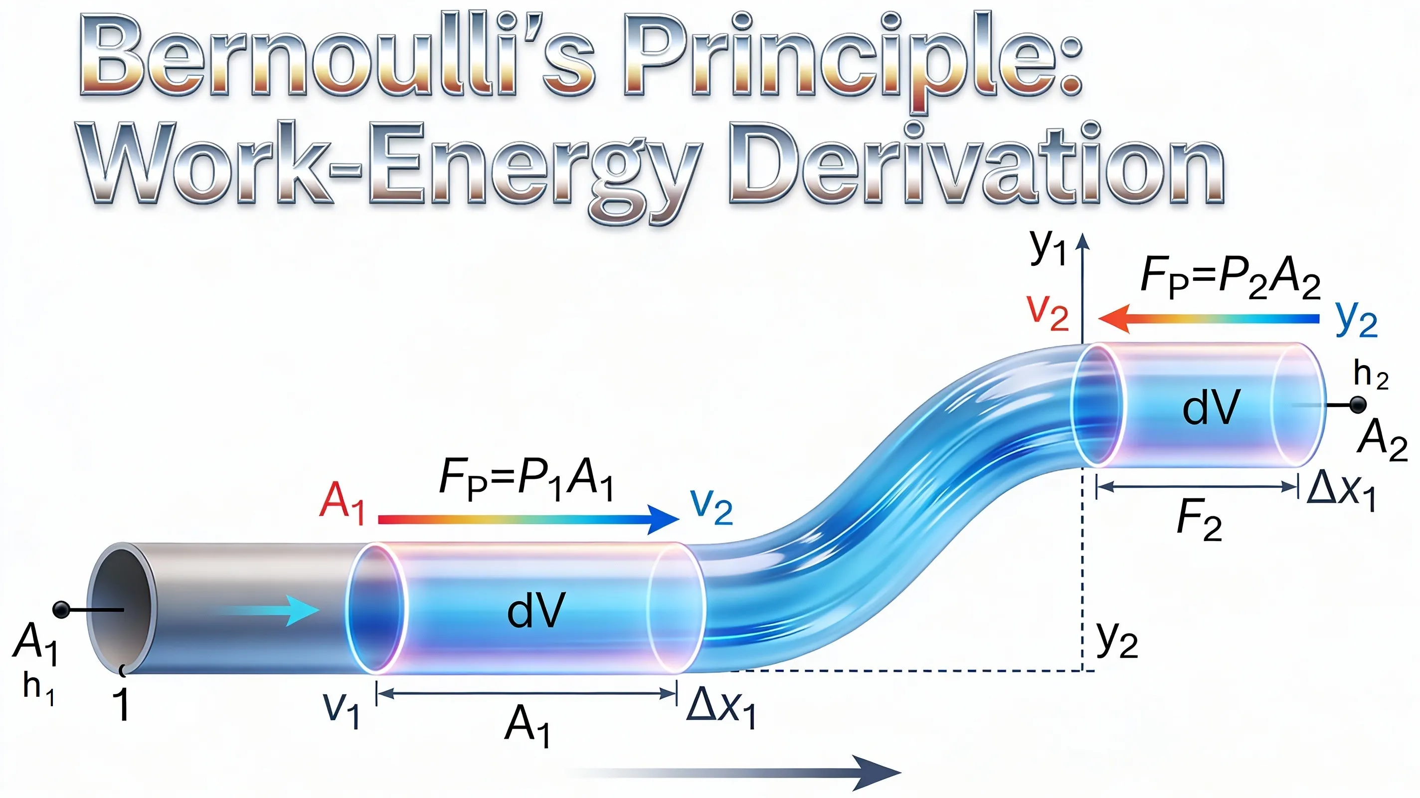
Bernoulli’s principle states that for a fluid flowing steadily along a streamline, the sum of its pressure energy, kinetic energy per unit volume, and gravitational potential energy per unit volume remains constant.

In simpler terms, when a fluid flows faster its pressure decreases, and when the flow slows down its pressure increases—provided the fluid is ideal and the flow is steady.

This principle was formulated by Daniel Bernoulli and represents an application of the law of conservation of energy to fluid motion.


Mathematical Form of Bernoulli’s Equation

For a fluid flowing along a streamline:

\[ P + \frac{1}{2}\rho v^2 + \rho g h = \text{constant} \]

Where

  • \(P\) = pressure of the fluid
  • \(\rho\) = density of the fluid
  • \(v\) = velocity of flow
  • \(h\) = height above reference level

Each term represents energy per unit volume of the fluid.


Derivation of Bernoulli’s Equation

Consider an incompressible, non-viscous fluid flowing steadily through a pipe of varying cross-section.

Let

  • At point 1: pressure \(P_1\), velocity \(v_1\), height \(h_1\)
  • At point 2: pressure \(P_2\), velocity \(v_2\), height \(h_2\)
Step 1: Work done by pressure forces

If a small volume \( \Delta V \) of fluid moves from point 1 to point 2:

\[ W_1 = P_1 \Delta V \] \[ W_2 = P_2 \Delta V \]

Net work done:

\[ W = (P_1 - P_2)\Delta V \]
Step 2: Change in kinetic energy

Mass of the fluid element:

\[ m = \rho \Delta V \]

Change in kinetic energy:

\[ \Delta KE = \frac{1}{2}\rho \Delta V (v_2^2 - v_1^2) \]
Step 3: Change in potential energy
\[ \Delta PE = \rho g \Delta V (h_2 - h_1) \]
Step 4: Apply work–energy theorem
\[ (P_1-P_2)\Delta V = \frac{1}{2}\rho\Delta V (v_2^2-v_1^2) + \rho g \Delta V (h_2-h_1) \]

Dividing by \( \Delta V \) and rearranging:

\[ P_1+\frac{1}{2}\rho v_1^2+\rho gh_1 = P_2+\frac{1}{2}\rho v_2^2+\rho gh_2 \]

This is the Bernoulli equation.


Conditions for Validity

  • Flow must be steady (streamline)
  • Fluid must be incompressible
  • Fluid must be non-viscous
  • Flow occurs along the same streamline
  • No external energy is added or removed

Important Applications

  • Venturimeter – measurement of fluid speed
  • Lift generated on an aeroplane wing
  • Atomizers and perfume sprays
  • Blowing air between two hanging papers
  • Magnus effect in spinning balls

Speed of Efflux: Torricelli’s Law

Speed of Efflux: Torricelli’s Law
Definition

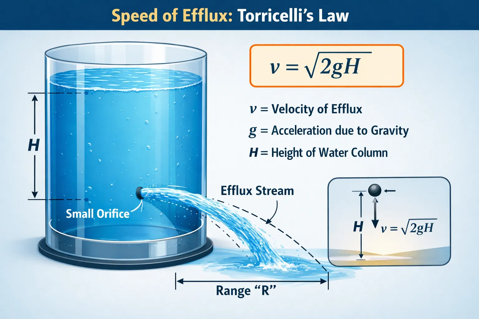
The speed of efflux is the speed with which a liquid emerges from a small orifice in the wall of a container filled with liquid when the orifice is exposed to the atmosphere.

Torricelli’s Law states that the speed of efflux of a liquid from an orifice is equal to the speed that a body would acquire if it freely fell through a vertical height equal to the depth of the orifice below the free surface of the liquid.

Mathematical Expression

\[ \boxed{v = \sqrt{2gh}} \]

Where

  • \(v\) = speed of efflux
  • \(h\) = vertical depth of the orifice below the liquid surface
  • \(g\) = acceleration due to gravity

This result can be obtained directly from Bernoulli’s equation by considering the liquid surface and the orifice as two points along the same streamline.


Important Observations

  • Independence from Liquid Density:
    Although pressure depends on density, the final expression for efflux speed does not contain density.
  • Dependence on Depth, Not Volume:
    The speed depends only on the depth \(h\) of the liquid above the orifice, not on the total volume of liquid in the container.
  • Small Orifice Condition:
    The orifice must be small compared to the tank’s cross-sectional area so that the velocity of the liquid surface is negligible.
  • Role of Atmospheric Pressure:
    When both the liquid surface and the orifice are exposed to the atmosphere, atmospheric pressure cancels out and does not affect the efflux speed.
  • Real Fluids vs Ideal Fluids:
    In real liquids, viscosity and turbulence reduce the actual speed, so the observed speed is slightly less than \( \sqrt{2gh} \).
  • Horizontal Range of the Jet:
    If the orifice is at height \(y\) above the ground, the horizontal range of the jet depends on both the efflux speed \(v\) and the time of fall.

Dynamic Lift

dynamic lift
(a) Fluid streaming past a static sphere. (b) Streamlines for a fluid around a sphere spinning clockwise. (c) Air flowing past an aerofoil.

Dynamic lift is the upward force experienced by a body moving through a fluid. This force arises due to the difference in pressure created by unequal fluid speeds around the body.

Dynamic lift occurs only when there is relative motion between the fluid and the body. It is a direct consequence of Bernoulli’s principle, which relates pressure and velocity in flowing fluids.


Derivation of Dynamic Lift (Using Bernoulli’s Principle)

Consider an aerofoil (airplane wing) moving horizontally through air under steady flow conditions.

Let:

  • \(v_1\) = speed of air above the wing
  • \(v_2\) = speed of air below the wing
  • \(P_1\) = pressure above the wing
  • \(P_2\) = pressure below the wing
  • \(\rho\) = density of air

Applying Bernoulli’s equation at the same horizontal level above and below the wing:

\[ P + \frac{1}{2}\rho v^2 = \text{constant} \]

Therefore,

\[ P_1 + \frac{1}{2}\rho v_1^2 = P_2 + \frac{1}{2}\rho v_2^2 \]

Rearranging,

\[ P_2 - P_1 = \frac{1}{2}\rho (v_1^2 - v_2^2) \]

Since the air moves faster above the wing (\(v_1 > v_2\)), the pressure above the wing becomes smaller (\(P_1 < P_2\)).


Expression for Lift Force

If \(A\) is the effective area of the wing, the lift force produced due to the pressure difference is

\[ L = (P_2 - P_1)A \]

Substituting the pressure difference:

\[ L = \frac{1}{2}\rho A (v_1^2 - v_2^2) \]

Thus, the lift force depends on the density of air, the area of the wing, and the difference in the squares of the air speeds above and below the wing.


Applications of Dynamic Lift

  • Flight of aeroplanes
  • Lift generated by birds during flight
  • Curving motion of spinning balls in sports (Magnus effect)
  • Design of aircraft wings and turbine blades

VISCOSITY

Definition

Viscosity is the intrinsic property of a fluid by virtue of which it opposes the relative motion between its adjacent layers while flowing. When one layer of a fluid moves faster than another, an internal resisting force arises that tends to reduce the velocity difference between the layers.

This resistance to flow is called viscous resistance, and the property responsible for it is called viscosity.

    In simple terms, viscosity measures the internal friction of a fluid.
  • Fluids with high viscosity (e.g., honey, glycerine) resist flow strongly.
  • Fluids with low viscosity (e.g., water, air) flow easily.

Physical Origin of Viscosity

The origin of viscosity differs in liquids and gases:

  • In liquids:
    Viscosity mainly arises due to intermolecular attraction. When layers slide past each other, these attractive forces resist their relative motion.
  • In gases:
    Viscosity originates from random molecular motion and the transfer of momentum between layers moving with different velocities.

Thus, viscosity is a macroscopic manifestation of microscopic molecular interactions.


Newton’s Law of Viscous Flow

For a fluid flowing steadily in parallel layers (laminar flow), the viscous force acting between adjacent layers is directly proportional to:

  • The area of contact between the layers
  • The velocity gradient perpendicular to the direction of flow
Mathematically
\[ F \propto A \frac{dv}{dy} \]

Introducing the constant of proportionality:

\[ F = \eta A \frac{dv}{dy} \]

where

  • \(F\) = viscous force
  • \(A\) = area of contact between layers
  • \(\frac{dv}{dy}\) = velocity gradient
  • \(\eta\) = coefficient of viscosity

Coefficient of Viscosity

The coefficient of viscosity (\(\eta\)) is defined as the viscous force per unit area required to maintain a unit velocity gradient between two parallel layers of fluid.

SI unit: Pascal-second (Pa·s)

\[ 1 \, Pa\cdot s = 1\,N\,s\,m^{-2} \]

Summary of Key Points

  • Viscosity is the internal resistance to flow in fluids.
  • Newton’s law of viscosity relates viscous force with velocity gradient.
  • Coefficient of viscosity measures the resistance of a fluid to flow.
  • Viscous force always opposes relative motion between fluid layers.
  • Temperature decreases viscosity in liquids but increases viscosity in gases.
  • Viscosity plays an important role in real fluid motion.

Stokes’ Law

Stokes’ Law states that when a small spherical body moves slowly through a viscous fluid, the resistive force (viscous drag) acting on it is directly proportional to the radius of the sphere, the velocity of the sphere, and the coefficient of viscosity of the fluid.

Mathematical Expression
\[ F = 6\pi \eta r v \]

where

  • \( \eta \) = coefficient of viscosity of the fluid
  • \( r \) = radius of the spherical body
  • \( v \) = velocity of the body relative to the fluid

Terminal Velocity from Force Balance

Consider a small sphere of radius \(r\) and density \( \rho_s \) falling through a liquid of density \( \rho_l \).

Forces Acting on the Sphere
Weight (downward)
\[ W = \frac{4}{3}\pi r^3 \rho_s g \]
Buoyant Force (upward)
\[ B = \frac{4}{3}\pi r^3 \rho_l g \]
Viscous Drag (upward)
\[ F = 6\pi \eta r v \]
Condition for Terminal Velocity

When the sphere reaches terminal velocity \(v_t\), the net force becomes zero.

\[ W = B + F \] Substituting the expressions: \[ \frac{4}{3}\pi r^3 \rho_s g = \frac{4}{3}\pi r^3 \rho_l g + 6\pi \eta r v_t \] Rearranging, \[ v_t = \frac{2r^2 g (\rho_s - \rho_l)}{9\eta} \]

This expression gives the terminal velocity of a sphere moving through a viscous fluid.


Important Aspects of Stokes’ Law

  • Validity Conditions:
    • The body must be spherical.
    • The motion must be slow (low Reynolds number).
    • The fluid should be viscous and incompressible.
    • The flow should remain laminar.
  • Linear Dependence on Velocity:
    The drag force increases directly with speed.
  • Role of Viscosity:
    Higher viscosity produces larger resistive force and hence smaller terminal velocity.
  • Size Dependence:
    Larger spheres experience greater viscous drag.
  • Terminal Velocity Concept:
    Explains why small droplets such as fog or mist fall very slowly.
  • Experimental Use:
    Stokes’ law is used to determine the viscosity of liquids by measuring terminal velocity.

SURFACE TENSION

Definition

Surface tension is the property of a liquid by virtue of which its free surface behaves like a stretched elastic membrane and tends to contract to the minimum possible surface area.

Quantitatively, surface tension is defined as the tangential force per unit length acting along the surface of a liquid and perpendicular to an imaginary line drawn on the surface.

Mathematical Expression
\[ T = \frac{F}{L} \]

where

  • \(T\) = surface tension
  • \(F\) = tangential force acting along the liquid surface
  • \(L\) = length along which the force acts

SI Unit: Newton per meter (N/m)


Molecular Explanation of Surface Tension

Inside a liquid, a molecule experiences equal attractive forces from neighboring molecules in all directions. Therefore, the net force acting on it is zero.

However, molecules at the surface experience an inward pull because there are fewer molecules above them. As a result, the surface molecules are pulled inward, making the surface behave like a stretched membrane.

This inward pull is responsible for the phenomenon of surface tension.


Important Properties of Surface Tension

  • Surface tension always acts along the liquid surface.
  • It acts perpendicular to any line drawn on the surface.
  • Surface tension tends to minimize the surface area of a liquid.
  • It decreases with increase in temperature.
  • Presence of impurities or detergents generally reduces surface tension.

Examples of Surface Tension

  • Formation of nearly spherical water droplets.
  • Needles or small insects can float on water.
  • Soap bubbles forming spherical shapes.
  • Water droplets forming on leaves.

Surface Energy

Surface energy is the energy possessed by the free surface of a liquid due to the unbalanced molecular forces acting on surface molecules.

Quantitatively, it is defined as the work required to increase the surface area of a liquid by unit area, while keeping the temperature constant.

Mathematically
\[ \text{Surface energy per unit area} = \frac{W}{A} \]

where \(W\) is the work done in increasing the surface area and \(A\) is the increase in surface area.

Surface energy represents the stored energy of a liquid surface and explains why liquid surfaces tend to contract and acquire minimum possible area.


Molecular Basis of Surface Energy

Molecules inside a liquid experience equal attractive forces from all directions, resulting in zero net force and minimum potential energy.

However, molecules at the surface experience unbalanced inward cohesive forces because there are fewer molecules above them. This increases their potential energy.

Therefore:

  • Surface molecules are in a higher energy state.
  • Extra energy is required to bring molecules from the interior to the surface.
  • This excess energy stored at the surface is called surface energy.

Proof: Surface Energy Equals Surface Tension per Unit Area

Consider a rectangular wire frame containing a thin liquid film with a movable wire of length \(L\).

Surface tension acts on the wire on both surfaces of the film.

\[ \text{Force} = 2TL \]

If the wire is displaced by a small distance \(dx\):

\[ dW = 2TL \, dx \]

Increase in surface area:

\[ dA = 2L \, dx \]

Thus,

\[ dW = T \, dA \]

Therefore,

\[ \boxed{\text{Surface energy per unit area} = T} \]

This shows that the surface energy per unit area of a liquid is numerically equal to its surface tension.


Important Aspects of Surface Energy

  • Unit and Dimensions
    • SI unit of surface energy: joule (J)
    • Surface energy per unit area: J m-2
    • Dimensions: [MT-2]
  • Relation with Surface Tension
    • Surface energy per unit area equals surface tension.
    • Both arise due to molecular cohesion.
  • Dependence on Temperature
    • Surface energy decreases as temperature increases.
    • It approaches zero at the critical temperature.
  • Effect of Impurities
    • Detergents and soaps reduce surface energy.
    • This helps spreading and cleaning action.
  • Double Surface in Films
    • Soap films have two surfaces.
    • Hence surface energy is twice that of a single liquid surface.
  • Difference from Internal Energy
    • Surface energy is associated only with surface molecules.
    • Internal energy involves all molecules of the liquid.

Applications and Physical Significance

  • Formation and stability of soap bubbles.
  • Floating of small objects like needles and insects on water.
  • Capillary rise and fall in thin tubes.
  • Wetting and non-wetting of surfaces.
  • Biological processes involving membranes.

Angle of Contact

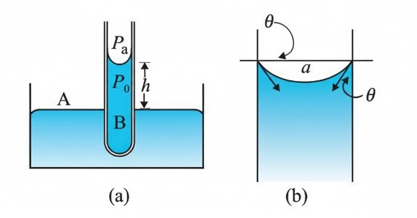
The angle of contact is defined as the angle between the tangent to the liquid surface at the point of contact and the solid surface, measured inside the liquid.

It is usually denoted by \( \theta \).

\[ \boxed{\text{Angle of Contact }(\theta)= \text{angle between liquid surface tangent and solid surface (inside liquid)}} \]

This angle determines whether a liquid wets a solid surface or does not wet it.


Molecular Origin of Angle of Contact

The angle of contact arises due to the competition between two types of intermolecular forces:

  • Adhesive force between liquid and solid molecules
  • Cohesive force between molecules of the liquid itself

The balance between these forces determines the shape of the liquid surface near the solid boundary and therefore fixes the value of \( \theta \).


Relation with Surface Tension

The angle of contact is governed by the equilibrium of surface tensions at the line of contact between:

  • Solid–air surface
  • Solid–liquid surface
  • Liquid–air surface

The balance of these surface tensions determines the curvature of the liquid surface and hence the value of the angle of contact.

Thus, the angle of contact is a consequence of surface tension and intermolecular forces.


Angle of Contact and Capillary Action

  • If \( \theta < 90^\circ \):
    The liquid wets the surface and rises in a capillary tube (example: water in glass).
  • If \( \theta > 90^\circ \):
    The liquid does not wet the surface and the level falls in a capillary tube (example: mercury in glass).
  • If \( \theta = 90^\circ \):
    No capillary rise or fall occurs.

Thus, the angle of contact plays a central role in the phenomenon of capillarity.

Drops and Bubbles

Liquids and gases, when free from external constraints, arrange themselves to minimize surface energy. This natural tendency leads to the formation of drops (liquid enclosed by air) and bubbles (gas enclosed by a thin liquid film).

Both phenomena are governed by surface tension, which produces an excess pressure across curved surfaces. The smaller the radius of curvature, the larger the required pressure difference.


Definition of a Liquid Drop

A liquid drop is a small quantity of liquid surrounded by air and having one free surface. Due to surface tension, a drop tends to become spherical because a sphere has the minimum surface area for a given volume.


Excess Pressure Inside a Liquid Drop

Consider a spherical liquid drop of radius \(r\) and surface tension \(T\).

Surface area: \[ A = 4\pi r^2 \] If the radius increases by \(dr\), \[ dA = 8\pi r\,dr \] Increase in surface energy: \[ dE = T\,dA = 8\pi rT\,dr \] Work done by excess pressure \( \Delta P \): \[ dW = \Delta P \times 4\pi r^2\,dr \] Equating work done and increase in surface energy: \[ \Delta P \cdot 4\pi r^2 dr = 8\pi rT dr \] \[ \boxed{\Delta P = \frac{2T}{r}} \]

Thus, the excess pressure inside a liquid drop is inversely proportional to its radius.


Definition of a Bubble

A soap bubble consists of gas enclosed by a thin liquid film. Unlike a liquid drop, a bubble has two free surfaces:

  • Inner liquid–gas surface
  • Outer liquid–air surface

Because of these two surfaces, the surface effects in bubbles are stronger than in drops.


Excess Pressure Inside a Soap Bubble

Let a soap bubble have radius \(r\) and surface tension \(T\).

Total surface area (two surfaces): \[ A = 2 \times 4\pi r^2 = 8\pi r^2 \] If the radius increases by \(dr\), \[ dA = 16\pi r\,dr \] Increase in surface energy: \[ dE = T\,dA = 16\pi rT\,dr \] Work done by excess pressure: \[ dW = \Delta P \cdot 4\pi r^2 dr \] Equating, \[ \Delta P \cdot 4\pi r^2 dr = 16\pi rT dr \] \[ \boxed{\Delta P = \frac{4T}{r}} \]

Thus, the excess pressure inside a soap bubble is twice the excess pressure inside a liquid drop of the same radius.

Capillary Rise

Capillary rise
Capillary rise: (a) Narrow tube immersed in water. (b) Enlarged view near the liquid surface.

Capillary rise is the vertical height through which a liquid rises (or falls) in a narrow tube when the tube is placed in the liquid. This phenomenon occurs due to the combined effect of surface tension and adhesive forces between the liquid and the walls of the tube.

If the liquid wets the tube (for example, water in glass), the liquid rises in the capillary tube. If the liquid does not wet the tube (for example, mercury in glass), the liquid level is depressed.


Derivation of Capillary Rise

Consider a vertical capillary tube of radius \(r\) dipped in a liquid of density \( \rho \). Let the surface tension of the liquid be \(T\) and the angle of contact be \( \theta \).

The liquid surface inside the tube becomes curved (concave for water in glass). Due to this curvature, a pressure difference exists across the liquid surface.

Pressure difference across the curved surface: \[ P_i - P_0 = \frac{2T}{R} \]

For a capillary tube, the radius of curvature of the meniscus is

\[ R = \frac{r}{\cos\theta} \] Therefore, \[ P_i - P_0 = \frac{2T \cos\theta}{r} \]

Now consider two points:

  • Point A: inside the liquid at the meniscus
  • Point B: at the liquid surface outside the tube

At equilibrium, the hydrostatic pressure difference balances the pressure difference due to surface tension:

\[ \rho g h = P_0 - P_i \] Substituting the previous relation: \[ \rho g h = \frac{2T \cos\theta}{r} \]

Formula for Capillary Rise

\[ \boxed{h = \frac{2T \cos\theta}{\rho g r}} \]

Thus, the height of capillary rise depends on surface tension, contact angle, density of the liquid, gravitational acceleration, and the radius of the tube.


Important Observations

  • Capillary rise is inversely proportional to the radius of the tube.
  • Liquids with larger surface tension rise higher in narrow tubes.
  • If \( \theta < 90^\circ \), the liquid rises (e.g., water in glass).
  • If \( \theta > 90^\circ \), the liquid level is depressed (e.g., mercury in glass).
  • Capillary action plays an important role in plants, ink flow in pens, and absorption of liquids in porous materials.

Example 1 — Pressure on Femur Bones

The two thigh bones (femurs), each of cross-sectional area \(10~\text{cm}^2\), support the upper part of a human body of mass \(40~\text{kg}\). Estimate the average pressure sustained by the femurs.


Concept / Theory

Pressure is defined as the force acting normally per unit area.

\[ P = \frac{F}{A} \]

where

  • \(P\) = pressure
  • \(F\) = force acting on the surface
  • \(A\) = area over which the force acts

In this problem, the force acting on the femur bones is the weight of the upper part of the body, and the pressure is distributed over the combined cross-sectional area of both femurs.

40 kg Femur Femur

Body weight supported by two femur bones

Solution

Step 1: Identify the given quantities

Cross-sectional area of each femur \[ A_1 = 10~\text{cm}^2 \] Mass of upper part of body \[ m = 40~\text{kg} \] Acceleration due to gravity \[ g = 9.8~\text{m s}^{-2} \]

Step 2: Convert area into SI units

\[ 1~\text{cm}^2 = 10^{-4}~\text{m}^2 \] Therefore, \[ A_1 = 10 \times 10^{-4}~\text{m}^2 \] Since two femurs support the body, \[ A = 2A_1 \] \[ A = 2 \times 10 \times 10^{-4} \] \[ A = 20 \times 10^{-4}~\text{m}^2 \]

Step 3: Calculate the force (weight of the body)
\[ F = mg \] \[ F = 40 \times 9.8 \] \[ F = 392~\text{N} \]
Step 4: Apply the pressure formula
\[ P = \frac{F}{A} \] \[ P = \frac{392}{20 \times 10^{-4}} \] \[ P = 1.96 \times 10^5~\text{N m}^{-2} \]
Final Result
\[ \boxed{P_{\text{avg}} \approx 2 \times 10^5~\text{N m}^{-2}} \]

Thus, the average pressure sustained by the femur bones is approximately \(2 \times 10^5~\text{Pa}\).

Example 2 — Pressure at a Depth in Water

What is the pressure on a swimmer \(10~\text{m}\) below the surface of a lake?


Concept / Theory

The pressure at a depth inside a liquid is greater than atmospheric pressure because the liquid above exerts additional weight.

The total pressure at depth \(h\) is given by

\[ P = P_a + \rho g h \]

where

  • \(P\) = total pressure at depth
  • \(P_a\) = atmospheric pressure at the surface
  • \(\rho\) = density of the liquid
  • \(g\) = acceleration due to gravity
  • \(h\) = depth below the liquid surface

Thus, the deeper we go in a liquid, the greater the pressure experienced.

Water Surface Swimmer h = 10 m

Pressure increases with depth in a liquid

Solution

Step 1: Write the given quantities

Depth of swimmer \[ h = 10~\text{m} \] Atmospheric pressure \[ P_a = 1.01 \times 10^{5}~\text{N m}^{-2} \] Density of water \[ \rho = 1 \times 10^{3}~\text{kg m}^{-3} \] Acceleration due to gravity \[ g = 10~\text{m s}^{-2} \]

Step 2: Use the pressure formula
\[ P = P_a + \rho g h \]
Step 3: Substitute the values
\[ P = 1.01 \times 10^{5} + (1 \times 10^{3})(10)(10) \]
Step 4: Simplify
\[ P = 1.01 \times 10^{5} + 1.0 \times 10^{5} \] \[ P = 2.01 \times 10^{5}~\text{N m}^{-2} \]
Final Result
\[ \boxed{P = 2.01 \times 10^{5}~\text{Pa}} \]

Therefore, the pressure experienced by the swimmer at a depth of \(10~\text{m}\) is approximately \(2.01 \times 10^{5}\,\text{Pa}\).

Example 3 — Height of the Atmosphere (Constant Density Approximation)

The density of the atmosphere at sea level is \(1.29~\text{kg m}^{-3}\). Assume that the density does not change with altitude. Estimate how high the atmosphere would extend.


Concept / Theory

The pressure at a depth in a fluid is given by the hydrostatic relation

\[ P = \rho g h \]

where

  • \(P\) = pressure at the bottom of the fluid column
  • \(\rho\) = density of the fluid
  • \(g\) = acceleration due to gravity
  • \(h\) = height of the fluid column

In this problem, we treat the atmosphere as a column of fluid with uniform density. The atmospheric pressure at sea level is therefore equal to the pressure produced by the weight of the air column above it.

h Atmosphere Earth's Surface

Atmosphere treated as a uniform fluid column

Solution

Step 1: Write the given quantities

Density of air \[ \rho = 1.29~\text{kg m}^{-3} \] Atmospheric pressure at sea level \[ P = 1.01 \times 10^{5}~\text{Pa} \] Acceleration due to gravity \[ g = 9.8~\text{m s}^{-2} \]

Step 2: Use the hydrostatic pressure relation
\[ P = \rho g h \] Rearranging for height \(h\): \[ h = \frac{P}{\rho g} \]
Step 3: Substitute the numerical values
\[ h = \frac{1.01 \times 10^{5}}{1.29 \times 9.8} \]
Step 4: Calculate the value
\[ h = 7989~\text{m} \] \[ h \approx 8 \times 10^{3}~\text{m} \]
Final Result
\[ \boxed{h \approx 8~\text{km}} \]

Therefore, if the density of air remained constant, the atmosphere would extend to about 8 km above sea level.

(In reality, air density decreases with altitude, so the atmosphere extends much higher than this estimate.)

Example 4 — Pressure on a Submarine at Great Depth

At a depth of \(1000~\text{m}\) in an ocean: (a) find the absolute pressure, (b) find the gauge pressure, (c) calculate the force acting on a submarine window of area \(20~\text{cm} \times 20~\text{cm}\). The interior of the submarine is maintained at sea-level atmospheric pressure. \((\rho = 1.03 \times 10^{3}\,\text{kg m}^{-3},\ g = 10\,\text{m s}^{-2})\)


Concept / Theory

In a liquid, pressure increases with depth due to the weight of the liquid column above. The pressure at depth \(h\) is given by:

\[ P = P_0 + \rho g h \]

where

  • \(P\) = absolute pressure at depth
  • \(P_0\) = atmospheric pressure at surface
  • \(\rho\) = density of the liquid
  • \(g\) = acceleration due to gravity
  • \(h\) = depth

The **gauge pressure** is the pressure due only to the liquid column:

\[ P_g = \rho g h \]

The force acting on a surface due to pressure difference is:

\[ F = \Delta P \times A \]
Ocean Surface h = 1000 m

Pressure increases with depth in water

Solution

Step 1: Given quantities
Depth \[ h = 1000~\text{m} \] Density of sea water \[ \rho = 1.03 \times 10^{3}~\text{kg m}^{-3} \] Acceleration due to gravity \[ g = 10~\text{m s}^{-2} \] Atmospheric pressure \[ P_0 = 1.01 \times 10^{5}~\text{Pa} \] Window area \[ A = 20\,\text{cm} \times 20\,\text{cm} \] Convert to SI units \[ A = 0.2\,\text{m} \times 0.2\,\text{m} \] \[ A = 0.04~\text{m}^2 \] # (a) Absolute Pressure \[ P = P_0 + \rho g h \] Substituting values: \[ P = 1.01 \times 10^{5} + (1.03 \times 10^{3})(10)(1000) \] \[ P = 1.01 \times 10^{5} + 1.03 \times 10^{7} \] \[ P = 1.0401 \times 10^{7}~\text{Pa} \] \[ \boxed{P \approx 1.04 \times 10^{7}\ \text{Pa}} \] This is approximately **104 atmospheres**. # (b) Gauge Pressure Gauge pressure is due to water column only: \[ P_g = \rho g h \] \[ P_g = (1.03 \times 10^{3})(10)(1000) \] \[ \boxed{P_g = 1.03 \times 10^{7}\ \text{Pa}} \] # (c) Force on Submarine Window Pressure difference across the window: \[ \Delta P = P - P_0 = \rho g h \] Force acting on window: \[ F = \Delta P \times A \] \[ F = (1.03 \times 10^{7}) (0.04) \] \[ F = 4.12 \times 10^{5}\ \text{N} \] \[ \boxed{F = 4.12 \times 10^{5}\ \text{N}} \]

Thus, the submarine window experiences a force of approximately \(4.12 \times 10^{5}\ \text{N}\) due to the surrounding water pressure.

Example 5 — Hydraulic Syringe System

Two syringes of different cross-sections (without needles) filled with water are connected by a tightly fitted rubber tube filled with water. The diameters of the smaller and larger pistons are \(1.0\ \text{cm}\) and \(3.0\ \text{cm}\) respectively.

(a) Find the force exerted on the larger piston when a force of \(10\ \text{N}\) is applied to the smaller piston. (b) If the smaller piston is pushed inward through \(6.0\ \text{cm}\), how much does the larger piston move out?


Concept / Theory

This system works on Pascal's Law, which states:

\[ \text{Pressure applied to a confined fluid is transmitted equally in all directions} \]

If two pistons are connected through an incompressible fluid, the pressures at the pistons are equal:

\[ \frac{F_1}{A_1} = \frac{F_2}{A_2} \]

Thus the force on the larger piston becomes:

\[ F_2 = F_1 \frac{A_2}{A_1} \]

Since the liquid is incompressible, the volume displaced by both pistons must be equal:

\[ A_1 L_1 = A_2 L_2 \]
Small piston Large piston F₁

Hydraulic transmission of force using Pascal’s law

Solution

Step 1: Given quantities
Smaller piston diameter \[ d_1 = 1.0\ \text{cm} \] Radius \[ r_1 = 0.5\ \text{cm} \] Larger piston diameter \[ d_2 = 3.0\ \text{cm} \] Radius \[ r_2 = 1.5\ \text{cm} \] Force on smaller piston \[ F_1 = 10\ \text{N} \] Displacement of smaller piston \[ L_1 = 6.0\ \text{cm} = 0.06\ \text{m} \] # (a) Force on the larger piston Using Pascal's law: \[ \frac{F_1}{A_1} = \frac{F_2}{A_2} \] \[ F_2 = F_1 \frac{A_2}{A_1} \] Area of piston \[ A = \pi r^2 \] Thus \[ \frac{A_2}{A_1} = \frac{\pi r_2^2}{\pi r_1^2} \] \[ \frac{A_2}{A_1} = \left(\frac{r_2}{r_1}\right)^2 \] \[ \frac{A_2}{A_1} = \left(\frac{1.5}{0.5}\right)^2 \] \[ \frac{A_2}{A_1} = 3^2 = 9 \] Therefore \[ F_2 = 10 \times 9 \] \[ \boxed{F_2 = 90\ \text{N}} \] # (b) Displacement of larger piston Because the liquid is incompressible: \[ A_1 L_1 = A_2 L_2 \] \[ L_2 = L_1 \frac{A_1}{A_2} \] \[ L_2 = 0.06 \times \frac{1}{9} \] \[ L_2 = 0.00667\ \text{m} \] Convert to centimeters: \[ L_2 \approx 0.67\ \text{cm} \] \[ \boxed{L_2 \approx 0.67\ \text{cm}} \]

Thus, the hydraulic system multiplies the force by a factor of 9, but the displacement of the larger piston becomes proportionally smaller.

Example 6 — Hydraulic Car Lift

In a car lift, compressed air exerts a force \(F_1\) on a small piston of radius \(5.0~\text{cm}\). This pressure is transmitted to a second piston of radius \(15~\text{cm}\). If the mass of the car to be lifted is \(1350~\text{kg}\), calculate the force \(F_1\). Also find the pressure required to lift the car. \((g = 9.8~\text{m s}^{-2})\)


Concept / Theory

Hydraulic car lifts work on Pascal’s Law, which states that pressure applied to an enclosed fluid is transmitted equally in all directions.

\[ \frac{F_1}{A_1} = \frac{F_2}{A_2} \]

where

  • \(F_1, A_1\) = force and area of the small piston
  • \(F_2, A_2\) = force and area of the large piston

The large piston supports the weight of the car.

Small piston Car F₁

Hydraulic car lift using Pascal’s principle

Solution

Step 1: Write the given quantities
Small piston radius \[ r_1 = 5.0~\text{cm} = 0.05~\text{m} \] Large piston radius \[ r_2 = 15~\text{cm} = 0.15~\text{m} \] Mass of car \[ m = 1350~\text{kg} \] Acceleration due to gravity \[ g = 9.8~\text{m s}^{-2} \]
Step 2: Force exerted by the car on the large piston
The large piston supports the weight of the car. \[ F_2 = mg \] \[ F_2 = 1350 \times 9.8 \] \[ F_2 = 13230~\text{N} \]
Step 3: Apply Pascal's law
\[ \frac{F_1}{A_1} = \frac{F_2}{A_2} \] \[ F_1 = F_2 \frac{A_1}{A_2} \] Area of piston: \[ A = \pi r^2 \] Thus \[ \frac{A_1}{A_2} = \frac{r_1^2}{r_2^2} \] \[ \frac{A_1}{A_2} = \frac{(0.05)^2}{(0.15)^2} \] \[ \frac{A_1}{A_2} = \frac{1}{9} \] Therefore \[ F_1 = 13230 \times \frac{1}{9} \] \[ \boxed{F_1 = 1470~\text{N}} \]
Step 4: Calculate the pressure applied
\[ P = \frac{F_1}{A_1} \] Area of small piston \[ A_1 = \pi r_1^2 \] \[ A_1 = \pi (0.05)^2 \] \[ A_1 = 0.00785~\text{m}^2 \] Now, \[ P = \frac{1470}{0.00785} \] \[ \boxed{P \approx 1.87 \times 10^5~\text{Pa}} \]

Thus, a force of approximately \(1470\ \text{N}\) applied on the small piston produces sufficient pressure to lift the car.

Example 7 — Lift on an Aircraft Wing

A fully loaded Boeing aircraft has a mass of \(3.3 \times 10^{5}\ \text{kg}\). Its total wing area is \(500\ \text{m}^2\). It flies horizontally with a speed of \(960\ \text{km h}^{-1}\).

(a) Estimate the pressure difference between the lower and upper surfaces of the wings. (b) Estimate the fractional increase in air speed over the upper surface compared to the lower surface. \((\rho = 1.2\ \text{kg m}^{-3})\)


Concept / Theory

The lift on an aircraft wing is produced due to the **pressure difference between the lower and upper surfaces** of the wing.

According to Bernoulli’s Principle, regions of faster fluid flow have lower pressure. Thus air moving faster above the wing creates lower pressure compared with the air below the wing.

The lift force equals the pressure difference multiplied by wing area:

\[ F = \Delta P \times A \]

During steady horizontal flight, the lift force balances the weight of the aircraft:

\[ \Delta P \times A = mg \]
Faster air (low pressure) Slower air (high pressure)

Lift generated due to pressure difference across the wing

Solution

Step 1: Write the given quantities
Mass of aircraft \[ m = 3.3 \times 10^{5}\ \text{kg} \] Wing area \[ A = 500\ \text{m}^2 \] Speed of aircraft \[ v = 960\ \text{km h}^{-1} \] Convert to SI units: \[ v = 960 \times \frac{5}{18} \] \[ v \approx 267\ \text{m s}^{-1} \] Density of air \[ \rho = 1.2\ \text{kg m}^{-3} \] Acceleration due to gravity \[ g = 9.8\ \text{m s}^{-2} \] # (a) Pressure Difference Across the Wings Lift force equals weight of aircraft: \[ \Delta P \times A = mg \] Therefore \[ \Delta P = \frac{mg}{A} \] Substitute values: \[ \Delta P = \frac{3.3 \times 10^{5} \times 9.8}{500} \] \[ \Delta P = 6.47 \times 10^{3}\ \text{Pa} \] \[ \boxed{\Delta P \approx 6.5 \times 10^{3}\ \text{Pa}} \] # (b) Fractional Increase in Air Speed Using Bernoulli’s equation between air below and above the wing: \[ P_1 + \frac{1}{2}\rho v_1^2 = P_2 + \frac{1}{2}\rho v_2^2 \] Thus \[ \Delta P = P_1 - P_2 \] \[ \Delta P = \frac{1}{2}\rho (v_2^2 - v_1^2) \] Using identity \[ v_2^2 - v_1^2 = (v_2+v_1)(v_2-v_1) \] \[ \Delta P = \frac{1}{2}\rho (v_2+v_1)(v_2-v_1) \] Assuming the average speed near the wing equals aircraft speed: \[ v_{\text{av}} = \frac{v_1 + v_2}{2} \approx 267\ \text{m s}^{-1} \] \[ v_1 + v_2 \approx 2v_{\text{av}} = 534\ \text{m s}^{-1} \] Now solve for velocity difference: \[ v_2 - v_1 = \frac{2\Delta P}{\rho (v_1 + v_2)} \] \[ v_2 - v_1 = \frac{2 \times 6.5 \times 10^3}{1.2 \times 534} \] \[ v_2 - v_1 \approx 20.3\ \text{m s}^{-1} \] Fractional increase in speed: \[ \frac{v_2 - v_1}{v_{\text{av}}} = \frac{20.3}{267} \] \[ \boxed{\approx 0.08 \; (\text{or } 8\%)} \]

Thus, the pressure difference required to support the aircraft is about \(6.5 \times 10^3\ \text{Pa}\), and the air speed above the wing must be roughly 8% higher than below the wing.

Example 8 — Determining Viscosity from Viscous Drag

A metal block of area \(0.10\ \text{m}^2\) is connected to a \(0.010\ \text{kg}\) mass via a string passing over an ideal pulley. A liquid film of thickness \(0.30\ \text{mm}\) is placed between the block and the table. When released, the block moves with constant speed \(0.085\ \text{m s}^{-1}\). Find the coefficient of viscosity of the liquid.


Concept / Theory

When a fluid flows between two parallel surfaces, a viscous force opposes the motion due to internal friction between fluid layers.

According to **Newton’s law of viscosity**, the viscous force is:

\[ F = \eta A \frac{dv}{dy} \]

For a liquid film of uniform thickness \(d\), the velocity gradient becomes:

\[ \frac{dv}{dy} = \frac{v}{d} \] Therefore, \[ F = \eta A \frac{v}{d} \]

In this problem the block moves with **constant velocity**, which means the net force is zero. Hence the **viscous drag force equals the pulling force due to the hanging mass**.

>Block Mass

Viscous resistance between block and liquid film

Solution

Step 1: Write the given quantities
Area of block \[ A = 0.10\ \text{m}^2 \] Mass of hanging body \[ m = 0.010\ \text{kg} \] Velocity of block \[ v = 0.085\ \text{m s}^{-1} \] Thickness of liquid film \[ d = 0.30\ \text{mm} \] Convert to SI units: \[ d = 3.0 \times 10^{-4}\ \text{m} \] Acceleration due to gravity \[ g = 9.8\ \text{m s}^{-2} \]
Step 2: Calculate tension in the string
Since the hanging mass is in equilibrium, \[ T = mg \] \[ T = 0.010 \times 9.8 \] \[ T = 0.098\ \text{N} \]
Step 3: Apply viscous force relation
At constant speed: \[ \text{Viscous force} = \text{Tension} \] \[ \eta A \frac{v}{d} = T \]
Step 4: Substitute the numerical values
\[ \eta \times 0.10 \times \frac{0.085}{3.0 \times 10^{-4}} = 0.098 \] Simplifying, \[ \eta \times 28.33 = 0.098 \]
Step 5: Solve for viscosity
\[ \eta = \frac{0.098}{28.33} \] \[ \eta \approx 3.46 \times 10^{-3}\ \text{Pa·s} \]
Final Result
\[ \boxed{\eta \approx 3.5 \times 10^{-3}\ \text{Pa·s}} \]

Thus, the coefficient of viscosity of the liquid film is approximately \(3.5 \times 10^{-3}\ \text{Pa·s}\).

Example 9 — Viscosity from Terminal Velocity (Stokes’ Law)

The terminal velocity of a copper ball of radius \(2.0\ \text{mm}\) falling through a tank of oil at \(20^\circ C\) is \(6.5\ \text{cm s}^{-1}\). Calculate the coefficient of viscosity of the oil. Density of oil \(=1.5\times10^{3}\ \text{kg m}^{-3}\), density of copper \(=8.9\times10^{3}\ \text{kg m}^{-3}\).


Concept / Theory

When a small sphere falls through a viscous liquid, three forces act on it:

  • Weight of the sphere (downward)
  • Buoyant force due to the liquid (upward)
  • Viscous drag force due to the fluid (upward)

As the sphere accelerates, viscous drag increases. Eventually the net force becomes zero and the sphere moves with constant speed called the terminal velocity.

At terminal velocity:

\[ \text{Effective weight} = \text{Viscous drag} \] Using **Stokes’ law**: \[ F_{viscous}=6\pi\eta r v_t \] Force balance becomes: \[ \frac{4}{3}\pi r^3 (\rho_c-\rho_o) g = 6\pi\eta r v_t \] Solving for viscosity: \[ \eta = \frac{2}{9}\frac{r^2(\rho_c-\rho_o)g}{v_t} \]
Weight Drag

Forces on a sphere falling through a viscous liquid

Solution

Step 1: Convert given quantities into SI units
Radius of copper ball \[ r = 2.0\ \text{mm} = 2.0\times10^{-3}\ \text{m} \] Terminal velocity \[ v_t = 6.5\ \text{cm s}^{-1} = 6.5\times10^{-2}\ \text{m s}^{-1} \] Density of copper \[ \rho_c = 8.9\times10^{3}\ \text{kg m}^{-3} \] Density of oil \[ \rho_o = 1.5\times10^{3}\ \text{kg m}^{-3} \] Acceleration due to gravity \[ g = 9.8\ \text{m s}^{-2} \]
Step 2: Apply Stokes’ law expression
\[ \eta = \frac{2}{9}\frac{r^2(\rho_c-\rho_o)g}{v_t} \]
Step 3: Substitute numerical values
\[ \eta = \frac{2}{9} \frac{(2.0\times10^{-3})^2(8.9\times10^{3}-1.5\times10^{3})9.8} {6.5\times10^{-2}} \]
Step 4: Simplify step-by-step
\[ (2.0\times10^{-3})^2 = 4.0\times10^{-6} \] \[ \rho_c-\rho_o = 7.4\times10^{3} \] Substituting, \[ \eta = \frac{2}{9} \frac{4.0\times10^{-6}\times7.4\times10^{3}\times9.8} {6.5\times10^{-2}} \] \[ \eta = \frac{2}{9}\times\frac{0.290}{0.065} \] \[ \eta \approx \frac{2}{9}\times4.46 \] \[ \eta \approx 0.99\ \text{Pa·s} \]
Final Result
\[ \boxed{\eta \approx 1.0\ \text{Pa·s}} \]

Thus, the coefficient of viscosity of the oil at \(20^\circ C\) is approximately \(1.0\ \text{Pa·s}\).

Example 10 — Pressure Required to Form a Bubble in Water

The lower end of a capillary tube of diameter \(2.00\ \text{mm}\) is dipped \(8.00\ \text{cm}\) below the surface of water. What pressure must be applied inside the tube to blow a hemispherical bubble at its end?

Surface tension of water \(= 7.30 \times 10^{-2}\ \text{N m}^{-1}\) Atmospheric pressure \(= 1.01 \times 10^{5}\ \text{Pa}\) Density of water \(= 1000\ \text{kg m}^{-3}\) \(g = 9.8\ \text{m s}^{-2}\)


Concept / Theory

To form a bubble at the end of the capillary tube, the pressure inside the tube must overcome two contributions:

  • Hydrostatic pressure due to the water column above the tube opening
  • Surface tension pressure due to the curved liquid surface of the bubble

Hydrostatic pressure at depth \(h\):

\[ P_{hyd} = \rho g h \]

Excess pressure due to surface tension for a hemispherical bubble:

\[ P_{st} = \frac{2T}{r} \]

Therefore, total excess pressure above atmospheric pressure is:

\[ P_{excess} = P_{hyd} + P_{st} \] The absolute pressure required in the tube is \[ P_{required} = P_{atm} + P_{excess} \]
h = 8 cm

Bubble formation at the end of a capillary tube immersed in water

Solution

Step 1: Radius of the capillary tube
\[ r = \frac{d}{2} \] \[ r = \frac{2.00\ \text{mm}}{2} \] \[ r = 1.00\ \text{mm} = 1.0 \times 10^{-3}\ \text{m} \]
Step 2: Hydrostatic pressure at depth
Depth \[ h = 8.00\ \text{cm} = 0.080\ \text{m} \] \[ P_{hyd} = \rho g h \] \[ P_{hyd} = 1000 \times 9.8 \times 0.080 \] \[ P_{hyd} = 784\ \text{Pa} \]
Step 3: Pressure due to surface tension
\[ P_{st} = \frac{2T}{r} \] \[ P_{st} = \frac{2 \times 7.30\times10^{-2}} {1.0\times10^{-3}} \] \[ P_{st} = 146\ \text{Pa} \]
Step 4: Total excess pressure
\[ P_{excess} = P_{hyd} + P_{st} \] \[ P_{excess} = 784 + 146 \] \[ P_{excess} = 930\ \text{Pa} \]
Step 5: Absolute pressure required
\[ P_{required} = P_{atm} + P_{excess} \] \[ P_{required} = 1.01\times10^5 + 930 \] \[ P_{required} = 1.0193\times10^5\ \text{Pa} \]
Final Results
\[ \boxed{P_{required} \approx 1.02 \times 10^5\ \text{Pa}} \] \[ \boxed{P_{excess} \approx 9.3 \times 10^2\ \text{Pa}} \]

Thus, the pressure required inside the tube to produce the hemispherical bubble is about \(1.02\times10^5\ \text{Pa}\), while the excess pressure above atmospheric pressure is \(9.3\times10^2\ \text{Pa}\).

Recent posts

    Share this Chapter

    Found this helpful? Share this chapter with your friends and classmates.


    💡 Exam Tip: Share helpful notes with your study group. Teaching others is one of the fastest ways to reinforce your own understanding.

    Frequently Asked Questions

    Mechanical properties of fluids describe how liquids and gases respond to forces, including their ability to flow, transmit pressure, resist motion, and show surface effects like viscosity and surface tension.

    A fluid is a substance that cannot resist shear stress in static condition and continuously deforms under even a small tangential force. Liquids and gases are fluids.

    Pressure is the normal force exerted per unit area by a fluid on any surface in contact with it, given by P = F/A.

    Pressure increases with depth according to P = P0 + ?gh, where ? is density, g is acceleration due to gravity, and h is depth.

    Pascal’s law states that pressure applied to an enclosed fluid is transmitted equally and undiminished to all parts of the fluid and the container walls.

    Pascal’s law is applied in hydraulic lifts, hydraulic brakes, hydraulic presses, and hydraulic jacks.

    Buoyant force is the upward force exerted by a fluid on an immersed body, opposing the weight of the body.

    A body immersed in a fluid experiences an upward force equal to the weight of the fluid displaced by it.

    Objects float if the buoyant force equals or exceeds their weight, usually when their average density is less than the fluid density.

    Viscosity is the internal resistance of a fluid to the relative motion between its layers.

    The coefficient of viscosity is the force per unit area required to maintain a unit velocity gradient between two parallel layers of a fluid.

    Stokes’ law states that the viscous force on a small sphere moving in a fluid is F = 6p?rv.

    Terminal velocity is the constant maximum velocity attained by a body falling through a viscous fluid when net force becomes zero.

    Terminal velocity is given by v = (2r²(? - s)g)/(9?).

    Surface tension is the property of a liquid surface that makes it behave like a stretched elastic membrane.

    MECHANICAL PROPERTIES OF FLUIDS – Learning Resources

    Get in Touch

    Let's Connect

    Questions, feedback, or suggestions?
    We'd love to hear from you.