Q1 A steel wire of length \(4.7\,m\) and cross-sectional area \(3.0\times10^{-5}\,m^2\) stretches by the same amount as a copper wire of length \(3.5\,m\) and cross-sectional area \(4.0\times10^{-5}\,m^2\) under the same load. Find the ratio of the Young’s modulus of steel to that of copper.
Concept Used
Young’s modulus measures the stiffness of a material and is defined as
\[ Y=\frac{\text{Stress}}{\text{Strain}} \]
For a wire stretched by a force \(F\),
\[ Y=\frac{FL}{A\Delta L} \]
where \(F\) = applied force \(L\) = original length \(A\) = cross-sectional area \(\Delta L\) = extension
Solution Strategy (Solution Map)
- Both wires experience the same force.
- Both wires undergo the same extension.
- Using \(Y=\dfrac{FL}{A\Delta L}\), take the ratio of Young’s moduli.
- Common quantities \(F\) and \(\Delta L\) cancel.
Given
Steel wire
\(L_s = 4.7\,m\)
\(A_s = 3.0\times10^{-5}\,m^2\)
Copper wire
\(L_c = 3.5\,m\)
\(A_c = 4.0\times10^{-5}\,m^2\)
Extension of both wires is the same: \(\Delta L\)
Step-by-Step Solution
Young’s modulus of steel:
\[ Y_s=\frac{F L_s}{A_s \Delta L} \]
Young’s modulus of copper:
\[ Y_c=\frac{F L_c}{A_c \Delta L} \]
Taking ratio,
\[ \frac{Y_s}{Y_c} = \frac{\dfrac{F L_s}{A_s \Delta L}} {\dfrac{F L_c}{A_c \Delta L}} \]
Cancelling common terms \(F\) and \(\Delta L\):
\[ \frac{Y_s}{Y_c} = \frac{L_s A_c}{L_c A_s} \]
Substituting values:
\[ \frac{Y_s}{Y_c} = \frac{4.7 \times 4.0\times10^{-5}} {3.5 \times 3.0\times10^{-5}} \]
\[ = \frac{4.7\times4}{3.5\times3} \]
\[ =\frac{18.8}{10.5} \approx 1.79 \]
Final Result
\[ \frac{Y_s}{Y_c}\approx 1.8 \]
The Young’s modulus of steel is about 1.8 times that of copper.
Physical Insight
- A higher Young’s modulus means the material is stiffer.
- Since \(Y_s > Y_c\), steel is stiffer than copper.
- This is why steel wires stretch less than copper wires under the same load.
Concept Diagram
Q2 Figure 8.9 shows the strain–stress curve for a given material. What are (a) Young’s modulus and (b) approximate yield strength for this material?
Concept Used
The stress–strain curve of a material describes how a material deforms under an applied load.
- Stress (\(\sigma\)) = Force per unit area.
- Strain (\(\varepsilon\)) = Fractional change in length.
- Young’s modulus is the slope of the linear elastic region of the stress–strain curve.
\[ Y=\frac{\sigma}{\varepsilon} \]
The yield strength is the stress at which the material begins to undergo plastic deformation.
Solution Strategy (Solution Map)
- Read a point from the linear elastic region of the graph.
- Calculate Young’s modulus using \(Y=\sigma/\varepsilon\).
- Locate the yield point on the graph to estimate yield strength.
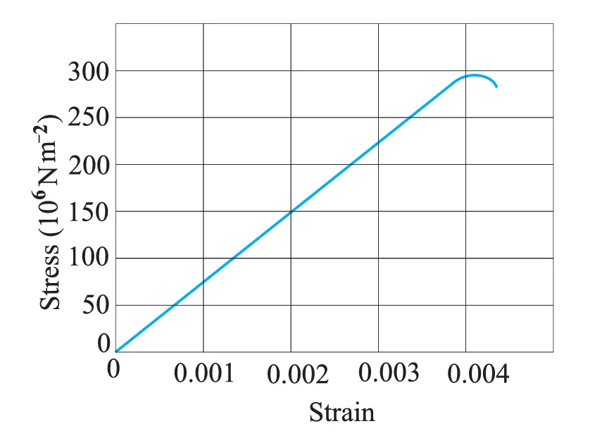
Step 1: Reading Values from Graph
From the straight (elastic) region of the graph:
\[ \sigma = 150\times10^6 \, N\,m^{-2} \]
\[ \varepsilon = 0.002 \]
Step 2: Calculating Young’s Modulus
\[ Y=\frac{\sigma}{\varepsilon} \]
\[ Y=\frac{150\times10^6}{0.002} \]
\[ Y=7.5\times10^{10}\ N\,m^{-2} \]
Thus, the Young’s modulus of the material is
\[ 7.5\times10^{10}\ N\,m^{-2} \]
Step 3: Determining Yield Strength
The yield point on the curve marks the beginning of plastic deformation.
From the graph, the stress at this point is approximately:
\[ \sigma_y \approx 300\times10^6\ N\,m^{-2} \]
\[ \sigma_y \approx 3.0\times10^8\ N\,m^{-2} \]
Hence, the approximate yield strength of the material is
\[ 3.0\times10^8\ N\,m^{-2} \]
Concept Insight
- The slope of the linear region of the stress–strain curve gives Young’s modulus.
- Beyond the yield point, deformation becomes permanent (plastic).
- Materials with larger Young’s modulus are stiffer.
Reference Diagram
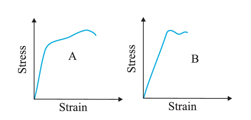
The stress–strain graphs for materials A and B are shown in Fig. 8.10. The graphs are drawn to the same scale. (a) Which of the materials has the greater Young’s modulus? (b) Which of the two is the stronger material?
Concept Used
- Young’s modulus measures the stiffness of a material.
- It is equal to the slope of the stress–strain curve in the elastic region.
- Strength of a material refers to the maximum stress it can withstand before breaking.
\[ Y = \frac{\text{Stress}}{\text{Strain}} \]
Solution Strategy (Solution Map)
- Compare the initial slopes of the two curves to determine Young’s modulus.
- Compare the maximum stress reached by each material to determine which is stronger.
(a) Material with Greater Young’s Modulus
Young’s modulus equals the slope of the initial straight portion of the stress–strain curve.
From the figure, the curve for material B rises more steeply than that of material A.
Since slope represents Young’s modulus,
Material B has the greater Young’s modulus.
This means material B is stiffer and produces less strain for the same applied stress.
(b) Stronger Material
The strength of a material is determined by the maximum stress it can withstand before breaking.
From the graph, material A reaches a higher maximum stress than material B before failure.
Therefore, material A is the stronger material.
Final Answers
- (a) Material B has the greater Young’s modulus.
- (b) Material A is the stronger material.
Exam Insight
- Stiffness ≠ Strength.
- A material can be very stiff but break at a lower stress.
- Always check:
- Slope → Young’s modulus
- Maximum stress → Strength
Reference Diagram
Read the following two statements carefully and state, with reasons, whether they are true or false. (a) The Young’s modulus of rubber is greater than that of steel. (b) The stretching of a coil is determined by its shear modulus.
Concept Used
- Young’s modulus (Y) measures resistance to longitudinal deformation.
- Shear modulus (G) measures resistance to shear deformation (change in shape without change in volume).
- In a helical spring, stretching produces twisting of the wire, which is a shear deformation.
(a) Statement: Young’s modulus of rubber is greater than that of steel
Answer: False
Young’s modulus represents the stiffness of a material.
Steel is very stiff and undergoes very little strain even under large stress. Rubber, however, stretches easily and shows large strain even under small stress.
Typical values illustrate this difference:
- Steel: \(Y \approx 2\times10^{11}\,N\,m^{-2}\)
- Rubber: \(Y \approx 10^{6}–10^{7}\,N\,m^{-2}\)
Therefore, the Young’s modulus of steel is much greater than that of rubber.
(b) Statement: The stretching of a coil is determined by its shear modulus
Answer: True
When a helical spring is stretched by a load, the wire of the spring does not simply extend. Instead, each turn of the wire undergoes twisting.
This twisting produces shear strain in the wire.
Since the deformation involved is shear deformation, the stretching of a spring depends on the shear modulus of the material.
Concept Insight
- Young’s modulus → stretching/compression of a straight wire.
- Shear modulus → twisting deformation.
- Helical springs stretch due to twisting of the wire, not direct elongation.
Illustration: Stretching of a Helical Spring
Final Answers
- (a) False
- (b) True
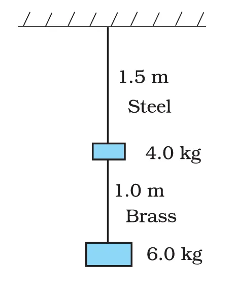
Q5 Two wires of diameter 0.25 cm, one made of steel and the other made of brass are loaded as shown in Fig. 8.11. The unloaded length of the steel wire is 1.5 m and that of the brass wire is 1.0 m. Compute the elongations of the steel and the brass wires.
Concept Used
The elongation of a wire under a load is given by
\[ \Delta L=\frac{FL}{AY} \]
where \(F\) = applied force \(L\) = original length of wire \(A\) = cross-sectional area \(Y\) = Young’s modulus of the material
Solution Strategy (Solution Map)
- Find the cross-sectional area of the wires from the given diameter.
- Determine the force acting on each wire from the masses shown in the figure.
- Use \( \Delta L=\frac{FL}{AY} \) separately for steel and brass wires.
Given
Diameter of each wire
\[ d = 0.25\,cm = 2.5\times10^{-3}\,m \]
Radius
\[ r = 0.125\,cm = 1.25\times10^{-3}\,m \]
Cross-sectional area
\[ A = \pi r^2 \]
\[ A = \pi (1.25\times10^{-3})^2 \approx 4.9\times10^{-6}\,m^2 \]
Lengths:
- Steel wire \(L_s = 1.5\,m\)
- Brass wire \(L_b = 1.0\,m\)
Young’s modulus:
- \(Y_s = 2\times10^{11}\,N\,m^{-2}\)
- \(Y_b = 1\times10^{11}\,N\,m^{-2}\)
Force on Each Wire
The steel wire supports both masses shown below it.
\[ F_s = (4 + 6)g = 10 \times 9.8 = 98\,N \]
The brass wire supports only the lower mass.
\[ F_b = 6 \times 9.8 = 58.8\,N \]
Elongation of Steel Wire
\[ \Delta L_s = \frac{F_s L_s}{A Y_s} \]
\[ \Delta L_s = \frac{98 \times 1.5} {4.9\times10^{-6}\times 2\times10^{11}} \]
\[ \Delta L_s \approx 1.5\times10^{-4}\,m \]
Elongation of Brass Wire
\[ \Delta L_b = \frac{F_b L_b}{A Y_b} \]
\[ \Delta L_b = \frac{58.8 \times 1.0} {4.9\times10^{-6}\times 1\times10^{11}} \]
\[ \Delta L_b \approx 1.2\times10^{-4}\,m \]
Final Results
- Elongation of steel wire = \(1.5\times10^{-4}\,m\)
- Elongation of brass wire = \(1.2\times10^{-4}\,m\)
Concept Insight
- Even though steel is stiffer (higher Young’s modulus), it elongates more here because it carries a larger load.
- Elongation depends on force, length, area, and material property.
Concept Diagram
Q6 The edge of an aluminium cube is 10 cm long. One face of the cube is firmly fixed to a vertical wall. A mass of 100 kg is attached to the opposite face of the cube. The shear modulus of aluminium is 25 GPa. What is the vertical deflection of this face?
Concept Used
Shear modulus measures the resistance of a material to shear deformation.
\[ G = \frac{\text{Shear stress}}{\text{Shear strain}} \]
For a block subjected to tangential force,
\[ G = \frac{F/A}{\Delta x/L} \]
Rearranging for deformation:
\[ \Delta x = \frac{F L}{A G} \]
Solution Strategy (Solution Map)
- Convert all quantities to SI units.
- Compute the force applied by the hanging mass.
- Calculate the area of the cube face.
- Substitute values into \( \Delta x = \frac{FL}{AG} \).
Given
- Edge of cube \(L = 10\,cm = 0.1\,m\)
- Mass attached \(m = 100\,kg\)
- Shear modulus \(G = 25\,GPa = 25\times10^9\,N\,m^{-2}\)
Step 1: Area of the Face
\[ A = (0.1)^2 \]
\[ A = 0.01\,m^2 \]
Step 2: Applied Force
\[ F = mg \]
\[ F = 100 \times 9.8 \]
\[ F = 980\,N \]
Step 3: Vertical Deflection
\[ \Delta x = \frac{FL}{AG} \]
\[ \Delta x = \frac{980 \times 0.1} {0.01 \times 25\times10^9} \]
\[ \Delta x = 3.92\times10^{-7}\,m \]
Final Result
\[ \Delta x = 3.92\times10^{-7}\,m \]
Vertical deflection ≈ 0.39 micrometres.
Concept Insight
- This deformation is extremely small because aluminium has a large shear modulus.
- Shear deformation involves change in shape without change in volume.
- The cube slightly distorts into a parallelepiped shape.
Shear Deformation Illustration
Q7 Four identical hollow cylindrical columns of mild steel support a structure of mass 50,000 kg. The inner and outer radii of each column are 30 cm and 60 cm respectively. Assuming the load distribution to be uniform, calculate the compressional strain of each column.
Concept Used
When a column supports a load, it undergoes compressive stress. The relation between stress, strain and Young’s modulus is
\[ Y = \frac{\text{Stress}}{\text{Strain}} \]
Hence,
\[ \text{Strain} = \frac{\text{Stress}}{Y} \]
Stress is defined as
\[ \sigma = \frac{F}{A} \]
Solution Strategy (Solution Map)
- Calculate the total weight of the structure.
- Determine the force supported by each column.
- Compute the cross-sectional area of the hollow cylindrical column.
- Find the compressive stress and then the strain using \(Y=\sigma/\varepsilon\).
Step 1: Total Weight of Structure
\[ W = mg \]
\[ W = 50{,}000 \times 9.8 \]
\[ W = 4.9\times10^{5}\,N \]
Step 2: Force on Each Column
Since four identical columns share the load uniformly,
\[ F = \frac{4.9\times10^{5}}{4} \]
\[ F = 1.225\times10^{5}\,N \]
Step 3: Cross-sectional Area of Column
Inner radius
\[ r = 30\,cm = 0.30\,m \]
Outer radius
\[ R = 60\,cm = 0.60\,m \]
Area of hollow cylinder:
\[ A = \pi(R^2 - r^2) \]
\[ A = \pi(0.60^2 - 0.30^2) \]
\[ A = \pi(0.36 - 0.09) \]
\[ A = 0.27\pi \]
\[ A \approx 0.848\,m^2 \]
Step 4: Compressive Stress
\[ \sigma = \frac{F}{A} \]
\[ \sigma = \frac{1.225\times10^{5}}{0.848} \]
\[ \sigma \approx 1.44\times10^{5}\,N\,m^{-2} \]
Step 5: Compressive Strain
Young’s modulus of mild steel:
\[ Y = 200\times10^{9}\,N\,m^{-2} \]
\[ \varepsilon = \frac{\sigma}{Y} \]
\[ \varepsilon = \frac{1.44\times10^{5}}{200\times10^{9}} \]
\[ \varepsilon \approx 7.2\times10^{-7} \]
Final Result
\[ \text{Compressional strain} = 7.2\times10^{-7} \]
(Strain is dimensionless.)
Concept Insight
- Even very large loads produce extremely small strain in steel because of its high Young’s modulus.
- Structural columns are often made hollow to reduce weight while maintaining strength.
Cross-Section of Hollow Column
Q8 A piece of copper having a rectangular cross-section of 15.2 mm × 19.1 mm is pulled in tension with a force of 44,500 N, producing only elastic deformation. Calculate the resulting strain.
Concept Used
When a material is stretched within its elastic limit, the relation between stress and strain is given by Young’s modulus:
\[ Y = \frac{\text{Stress}}{\text{Strain}} \]
Hence,
\[ \varepsilon = \frac{\sigma}{Y} \]
where
- \(\sigma = \frac{F}{A}\) (stress)
- \(F\) = applied force
- \(A\) = cross-sectional area
- \(Y\) = Young’s modulus
Solution Strategy (Solution Map)
- Convert the cross-sectional dimensions into SI units.
- Calculate the cross-sectional area.
- Determine the stress using \( \sigma = F/A \).
- Calculate strain using \( \varepsilon = \sigma/Y \).
Given
- Force applied \(F = 44{,}500\,N\)
- Dimensions of cross-section: \(15.2\,mm \times 19.1\,mm\)
- Young’s modulus of copper \(Y = 110\times10^{9}\,N\,m^{-2}\)
Step 1: Convert Dimensions to SI Units
\[ 15.2\,mm = 15.2\times10^{-3}\,m \]
\[ 19.1\,mm = 19.1\times10^{-3}\,m \]
Step 2: Cross-sectional Area
\[ A = 15.2\times10^{-3} \times 19.1\times10^{-3} \]
\[ A = 2.90\times10^{-4}\,m^2 \]
Step 3: Stress Produced
\[ \sigma = \frac{F}{A} \]
\[ \sigma = \frac{44{,}500}{2.90\times10^{-4}} \]
\[ \sigma \approx 1.53\times10^{8}\,N\,m^{-2} \]
Step 4: Resulting Strain
\[ \varepsilon = \frac{\sigma}{Y} \]
\[ \varepsilon = \frac{1.53\times10^{8}} {110\times10^{9}} \]
\[ \varepsilon \approx 1.39\times10^{-3} \]
Final Result
\[ \text{Strain} \approx 1.4\times10^{-3} \]
(Strain is dimensionless.)
Concept Insight
- The strain is small because copper has a large Young’s modulus.
- The deformation is purely elastic, meaning the copper returns to its original shape when the force is removed.
Rectangular Cross-Section
Q9 A steel cable with a radius of 1.5 cm supports a chairlift at a ski area. If the maximum stress is not to exceed \(10^{8}\,N\,m^{-2}\), what is the maximum load the cable can support?
Concept Used
Stress is defined as force acting per unit area.
\[ \sigma = \frac{F}{A} \]
where \(F\) = force (load) \(A\) = cross-sectional area \(\sigma\) = stress.
Solution Strategy (Solution Map)
- Find the cross-sectional area of the cable using \(A=\pi r^2\).
- Use the relation \(F = \sigma A\).
- Substitute the given maximum stress.
Given
- Radius of cable \(r = 1.5\,cm = 0.015\,m\)
- Maximum permissible stress \(\sigma = 10^{8}\,N\,m^{-2}\)
Step 1: Cross-Sectional Area
\[ A = \pi r^2 \]
\[ A = 3.14(0.015)^2 \]
\[ A = 7.07\times10^{-4}\,m^2 \]
Step 2: Maximum Load
\[ F = \sigma A \]
\[ F = 10^{8} \times 7.07\times10^{-4} \]
\[ F = 7.07\times10^{4}\,N \]
Final Result
\[ \text{Maximum load} = 7.07\times10^{4}\,N \]
Concept Insight
- A thicker cable can support larger loads because the cross-sectional area increases.
- Engineering structures always limit the stress below a safe value to avoid failure.
Cable Cross-Section
Q10 A rigid bar of mass 15 kg is supported symmetrically by three wires each 2.0 m long. Those at each end are of copper and the middle one is of iron. Determine the ratios of their diameters if each is to have the same tension.
Concept Used
For a wire under tension, the extension is given by
\[ \Delta L = \frac{T L}{A Y} \]
where
- \(T\) = tension
- \(L\) = original length
- \(A\) = cross-sectional area
- \(Y\) = Young’s modulus
Since the bar is rigid and supported symmetrically, the three suspension points must move down by the same amount. Therefore, all three wires undergo the same extension.
Solution Strategy (Solution Map)
- Use the elongation formula \( \Delta L = \frac{TL}{AY} \).
- Since \(T\), \(L\), and \(\Delta L\) are the same for all wires, compare \(A\) and \(Y\).
- Use the relation \(A = \pi r^2\) to obtain the ratio of radii (and hence diameters).
Given
- Length of each wire \(L = 2.0\,m\)
- Young’s modulus of iron \(Y_{Fe} = 190\times10^{9}\,N\,m^{-2}\)
- Young’s modulus of copper \(Y_{Cu} = 110\times10^{9}\,N\,m^{-2}\)
Step 1: Relation for Extension
For iron wire
\[ \Delta L = \frac{T L}{A_{Fe} Y_{Fe}} \]
For copper wire
\[ \Delta L = \frac{T L}{A_{Cu} Y_{Cu}} \]
Since the extension of all wires is the same,
\[ \frac{T L}{A_{Fe} Y_{Fe}} = \frac{T L}{A_{Cu} Y_{Cu}} \]
Cancelling \(T\) and \(L\),
\[ A_{Fe}Y_{Fe} = A_{Cu}Y_{Cu} \]
Step 2: Area Relation
\[ \frac{A_{Cu}}{A_{Fe}} = \frac{Y_{Fe}}{Y_{Cu}} \]
\[ \frac{A_{Cu}}{A_{Fe}} = \frac{190\times10^{9}}{110\times10^{9}} \]
\[ \frac{A_{Cu}}{A_{Fe}} = \frac{19}{11} \]
Step 3: Convert Area to Radius
Since \(A = \pi r^2\),
\[ \frac{r_{Cu}^{2}}{r_{Fe}^{2}} = \frac{19}{11} \]
\[ \frac{r_{Cu}}{r_{Fe}} = \sqrt{\frac{19}{11}} \]
\[ \frac{r_{Cu}}{r_{Fe}} \approx 1.3 \]
Since diameter is proportional to radius,
\[ \frac{d_{Cu}}{d_{Fe}} = 1.3 \]
Final Result
Diameter ratio (Copper : Iron) = 1.3 : 1
Concept Insight
- Materials with smaller Young’s modulus stretch more for the same tension.
- Copper has a smaller Young’s modulus than iron, so its wire must be thicker to keep the extension equal.
Support Wire Arrangement
Q11 A 14.5 kg mass, fastened to the end of a steel wire of unstretched length 1.0 m, is whirled in a vertical circle with an angular velocity of 2 rev/s at the bottom of the circle. The cross-sectional area of the wire is 0.065 cm². Calculate the elongation of the wire when the mass is at the lowest point of its path.
Concept Used
At the lowest point of vertical circular motion, the tension in the wire must provide:
- The weight of the body \(mg\)
- The centripetal force \(mv^2/r\)
\[ T = mg + \frac{mv^2}{r} \]
The elongation of the wire due to tension is given by
\[ \Delta L = \frac{TL}{AY} \]
Solution Strategy (Solution Map)
- Convert angular speed to rad/s.
- Calculate the tension at the lowest point.
- Find the stress and strain in the wire.
- Use strain to determine elongation.
Given
- Mass \(m = 14.5\,kg\)
- Length of wire \(L = 1.0\,m\)
- Angular speed \(2\,rev\,s^{-1}\)
- Area \(A = 0.065\,cm^2 = 0.065\times10^{-4}\,m^2\)
- Young’s modulus of steel \(Y = 2\times10^{11}\,N\,m^{-2}\)
Step 1: Angular Velocity
\[ \omega = 2 \times 2\pi \]
\[ \omega = 4\pi \,rad\,s^{-1} \]
Step 2: Tension at Lowest Point
\[ T = mg + mr\omega^2 \]
\[ T = (14.5\times9.8) + (14.5\times1\times(4\pi)^2) \]
\[ T \approx 142 + 229 \]
\[ T \approx 371\,N \]
Step 3: Stress in the Wire
\[ \sigma = \frac{T}{A} \]
\[ \sigma = \frac{371}{0.065\times10^{-4}} \]
Step 4: Strain
\[ \varepsilon = \frac{\sigma}{Y} \]
\[ \varepsilon = \frac{371}{0.065\times10^{-4}\times2\times10^{11}} \]
\[ \varepsilon \approx 2.85\times10^{-4} \]
Step 5: Elongation
\[ \Delta L = \varepsilon L \]
\[ \Delta L = 2.85\times10^{-4}\times1 \]
\[ \Delta L \approx 2.9\times10^{-4}\,m \]
Final Result
\[ \Delta L \approx 2.9\times10^{-4}\,m \]
Concept Insight
- The tension is maximum at the lowest point because the wire must support both weight and centripetal force.
- Even large forces produce very small elongation because steel has a very high Young’s modulus.
Vertical Circular Motion
Q12
Where Maximum Stress Occurs in Real Systems
Concepts such as stress, strain, Young’s modulus, and bulk modulus are not just theoretical. They determine how real engineering structures behave under loads. Understanding where maximum stress occurs helps engineers design safe bridges, elevators, cables, and rotating machines.
1. Bridges and Structural Beams
In bridges or beams, the maximum stress usually occurs at the points of support or near the center, depending on how the load is applied.
- The upper layers of a beam experience compression.
- The lower layers experience tension.
- The central region where bending is largest experiences the maximum stress.
2. Elevators and Suspension Cables
Elevator cables and suspension bridge cables experience their maximum stress when the load is largest.
- When the elevator starts upward acceleration, tension increases.
- The cable must support both weight and acceleration forces.
- Engineers design cables so that stress remains below the safe stress limit.
3. Rotating Systems (Circular Motion)
In rotating systems such as a mass whirled in a circle or rotating machinery, the string or rod experiences the maximum tension at the lowest point.
- The tension must provide both weight and centripetal force.
- This is why wires or rods in rotating systems must be very strong.
Key Takeaway
- Maximum stress occurs where the combined forces are greatest.
- Understanding stress helps engineers design safe structures and machines.
- Elasticity concepts from physics are essential in civil, mechanical, and aerospace engineering.
Concept Used
The bulk modulus measures the resistance of a substance to compression.
B = -\frac{\Delta P}{\Delta V/V}
Ignoring the negative sign (which only indicates decrease in volume):
\[ B = \frac{\Delta P}{\Delta V/V} \]
Solution Strategy
- Convert all quantities to SI units.
- Calculate the change in pressure.
- Determine fractional change in volume.
- Substitute into the bulk modulus formula.
Step 1: Convert Volume to SI Units
\[ V = 100\ \text{litre} = 100 \times 10^{-3}\ m^3 \]
\[ V = 0.1\ m^3 \]
Final volume = \(100.5\) litre
\[ \Delta V = 100.5 - 100.0 \]
\[ \Delta V = 0.5\ \text{litre} = 0.5 \times 10^{-3}\ m^3 \]
Step 2: Pressure Increase
\[ \Delta P = 100 \times 1.013 \times 10^{5} \]
\[ \Delta P = 1.013 \times 10^{7}\ Pa \]
Step 3: Bulk Modulus Calculation
\[ B = \frac{\Delta P}{\Delta V/V} \]
\[ B = \frac{PV}{\Delta V} \]
\[ B = \frac{1.013\times10^{7} \times 0.1}{0.5\times10^{-3}} \]
\[ B = 2.026\times10^{9}\ Pa \]
Final Result
Bulk modulus of water ≈ \(2.0 \times 10^{9}\ Pa\)
Comparison with Air
The bulk modulus of air at constant temperature is approximately
\[ B_{air} \approx 10^{5}\ Pa \]
Therefore,
\[ \frac{B_{water}}{B_{air}} \approx 10^{4} \]
Water is about ten thousand times less compressible than air.
Concept Insight
- Water molecules are closely packed.
- Even large pressure produces very small volume change.
- Air molecules are far apart, so air compresses easily.
Physical Meaning
Liquids are nearly incompressible because intermolecular spaces are very small. Gases have large intermolecular gaps, making them easy to compress.
Q13 What is the density of water at a depth where pressure is 80.0 atm, given that its density at the surface is \(1.03\times10^{3}\,kg\,m^{-3}\)?
Concept Used
The bulk modulus of a substance measures its resistance to compression.
\[ B = -\frac{\Delta P}{\Delta V/V} \]
For liquids, a small increase in pressure produces a small increase in density. Using the relation between density change and pressure change:
\[ \frac{\Delta \rho}{\rho_0} = \frac{\Delta P}{B} \]
Solution Strategy (Solution Map)
- Determine the increase in pressure relative to surface pressure.
- Use the bulk modulus relation to calculate the change in density.
- Add this change to the original density.
Given
- Surface density \( \rho_0 = 1.03\times10^{3}\,kg\,m^{-3} \)
- Pressure at depth \( = 80\,atm \)
- Bulk modulus of water \( B = 2.2\times10^{9}\,Pa \)
- \(1\,atm = 1.013\times10^{5}\,Pa\)
Step 1: Pressure Increase
Surface pressure = \(1\,atm\)
\[ \Delta P = (80 - 1)\,atm \]
\[ \Delta P = 79 \times 1.013\times10^{5} \]
\[ \Delta P \approx 8.0\times10^{6}\,Pa \]
Step 2: Change in Density
\[ \frac{\Delta \rho}{\rho_0} = \frac{\Delta P}{B} \]
\[ \Delta \rho = \rho_0 \frac{\Delta P}{B} \]
\[ \Delta \rho = 1.03\times10^{3} \times \frac{8.0\times10^{6}} {2.2\times10^{9}} \]
\[ \Delta \rho \approx 3.75\,kg\,m^{-3} \]
Step 3: Density at Depth
\[ \rho = \rho_0 + \Delta \rho \]
\[ \rho = 1.03\times10^{3} + 3.75 \]
\[ \rho \approx 1.034\times10^{3}\,kg\,m^{-3} \]
Final Result
Density at 80 atm ≈ 1.034 × 10³ kg m⁻³
Concept Insight
- Liquids like water are very difficult to compress.
- Even a pressure increase of nearly 80 atm produces only a very small change in density.
- This is why water behaves almost as an incompressible fluid in most engineering calculations.
Compression of Liquid Under Pressure
Q14 Compute the fractional change in volume of a glass slab when subjected to a hydraulic pressure of 10 atm.
Concept Used
The bulk modulus of a material measures its resistance to volume compression.
\[ B = -\frac{\Delta P}{\Delta V / V} \]
Ignoring the negative sign (which only indicates decrease in volume), the magnitude of fractional change in volume is
\[ \frac{\Delta V}{V} = \frac{P}{B} \]
Solution Strategy (Solution Map)
- Convert the pressure from atm to pascal.
- Use the bulk modulus relation.
- Calculate the fractional change in volume.
Given
- Hydraulic pressure \(P = 10\,atm\)
- \(1\,atm = 1.013\times10^{5}\,Pa\)
- Bulk modulus of glass \(B = 37\times10^{9}\,Pa\)
Step 1: Convert Pressure to SI Units
\[ P = 10 \times 1.013\times10^{5} \]
\[ P = 1.013\times10^{6}\,Pa \]
Step 2: Fractional Change in Volume
\[ \frac{\Delta V}{V} = \frac{P}{B} \]
\[ \frac{\Delta V}{V} = \frac{1.013\times10^{6}} {37\times10^{9}} \]
\[ \frac{\Delta V}{V} \approx 2.7\times10^{-5} \]
Final Result
Fractional change in volume ≈ 2.7 × 10⁻⁵
(The volume decreases by this small fraction.)
Concept Insight
- Solids like glass have a very large bulk modulus.
- Therefore, even large pressures produce only a very small change in volume.
- This is why most solids appear nearly incompressible in everyday situations.
Compression of Solid Under Pressure
Q15 Determine the volume contraction of a solid copper cube, 10 cm on an edge, when subjected to a hydraulic pressure of \(7.0 \times 10^{6}\,Pa\).
Concept Used
The bulk modulus measures resistance of a material to volume compression.
\[ B = -\frac{\Delta P}{\Delta V/V} \]
Ignoring the negative sign (which indicates reduction in volume),
\[ \Delta V = \frac{PV}{B} \]
Solution Strategy (Solution Map)
- Find the initial volume of the cube.
- Use the bulk modulus relation to determine fractional volume change.
- Calculate the actual volume contraction.
Given
- Edge of cube \(=10\,cm = 0.1\,m\)
- Hydraulic pressure \(P = 7.0\times10^{6}\,Pa\)
- Bulk modulus of copper \(B = 140\times10^{9}\,Pa\)
Step 1: Volume of the Cube
\[ V = (0.1)^3 \]
\[ V = 0.001\,m^3 \]
Step 2: Volume Contraction
\[ \Delta V = \frac{PV}{B} \]
\[ \Delta V = \frac{7.0\times10^{6} \times 0.001} {140\times10^{9}} \]
\[ \Delta V = \frac{7.0\times10^{3}}{1.4\times10^{11}} \]
\[ \Delta V = 5.0\times10^{-8}\,m^3 \]
Final Result
Volume contraction ≈ 5.0 × 10⁻⁸ m³
(The cube shrinks by this very small volume.)
Concept Insight
- Copper has a very large bulk modulus.
- Even under very large pressure, the volume change is extremely small.
- This is why most solids appear nearly incompressible in everyday situations.
Compression of Copper Cube
How much should the pressure on a litre of water be changed to compress it by 0.10%?
Concept Used
The bulk modulus relates the change in pressure to the fractional change in volume.
\[ B = -\frac{\Delta P}{\Delta V/V} \]
Ignoring the negative sign (which indicates reduction in volume), the pressure change is
\[ \Delta P = B\left(\frac{\Delta V}{V}\right) \]
Solution Strategy (Solution Map)
- Convert the percentage compression into fractional volume change.
- Use the bulk modulus of water.
- Calculate the required pressure change.
Given
- Initial volume \(V = 1\,\text{litre} = 1\times10^{-3}\,m^3\)
- Compression \(=0.10\%\)
- Bulk modulus of water \(B = 2.2\times10^{9}\,Pa\)
Step 1: Fractional Change in Volume
\[ \frac{\Delta V}{V} = \frac{0.10}{100} \]
\[ \frac{\Delta V}{V} = 1.0\times10^{-3} \]
Step 2: Required Pressure Change
\[ \Delta P = B\left(\frac{\Delta V}{V}\right) \]
\[ \Delta P = 2.2\times10^{9}\times1.0\times10^{-3} \]
\[ \Delta P = 2.2\times10^{6}\,Pa \]
Final Result
Required pressure increase ≈ 2.2 × 10⁶ Pa
Concept Insight
- Liquids have a very large bulk modulus, meaning they resist compression.
- Even a tiny compression of 0.10% requires a very large pressure.
- This is why liquids are treated as nearly incompressible fluids in many physical calculations.
Compression of Liquid
Mechanical Properties of Solids – All Formulas in One Place
Quick revision sheet for NCERT Class XI Physics Chapter 8. These formulas cover almost all numerical problems in the chapter.
1. Stress
Stress is the restoring force acting per unit area.
\[ \sigma = \frac{F}{A} \]
- \(F\) = Applied force
- \(A\) = Cross-sectional area
2. Strain
Strain is the fractional change in dimension.
\[ \text{Strain} = \frac{\Delta L}{L} \]
- \(\Delta L\) = change in length
- \(L\) = original length
3. Young’s Modulus
Measures resistance to stretching or compression.
\[ Y = \frac{\text{Stress}}{\text{Strain}} \]
\[ Y = \frac{FL}{A\Delta L} \]
4. Shear Modulus
Measures resistance to change in shape.
\[ G = \frac{\text{Shear Stress}}{\text{Shear Strain}} \]
\[ G = \frac{F/A}{\Delta x/L} \]
5. Bulk Modulus
Measures resistance to volume compression.
\[ B = -\frac{\Delta P}{\Delta V/V} \]
Magnitude relation:
\[ \frac{\Delta V}{V} = \frac{P}{B} \]
6. Elongation of a Wire
\[ \Delta L = \frac{FL}{AY} \]
7. Energy Stored in a Stretched Wire
\[ U = \frac{1}{2}F\Delta L \]
\[ U = \frac{1}{2}\sigma \varepsilon V \]
8. Stress–Strain Curve Key Points
- Proportional limit – Stress proportional to strain.
- Elastic limit – Material returns to original shape.
- Yield point – Plastic deformation begins.
- Ultimate stress – Maximum stress before failure.
- Breaking point – Material fractures.
Visual Summary: Stress–Strain Curve
Quick Exam Tips
- Always convert cm² → m² before calculations.
- Strain is dimensionless.
- Young’s modulus problems usually reduce to \(\Delta L = FL/AY\).
- Bulk modulus problems use \(\Delta V/V = P/B\).
💡 Revision Tip: If you remember these formulas and understand the stress–strain curve, you can solve almost every numerical problem in this chapter.
Top 10 Conceptual Mistakes Students Make in Mechanical Properties of Solids
Before exams, many students lose marks due to small conceptual mistakes. Here are the most common errors and how to avoid them.
1. Confusing Stress and Pressure
Mistake: Treating stress and pressure as different concepts. Reality: Both are force per unit area.
\[ \sigma = \frac{F}{A} \]
Quick Fix: Remember that pressure is simply normal stress.
2. Forgetting Unit Conversion (cm² → m²)
Mistake: Using cross-sectional area in cm².
Quick Fix:
\[ 1\,cm^2 = 10^{-4}\,m^2 \]
3. Mixing Up Stress–Strain and Force–Extension Graphs
Mistake: Interpreting slopes incorrectly.
- Slope of stress–strain graph → Young’s modulus
- Slope of force–extension graph → spring constant
4. Ignoring Equal Extension Condition
In many NCERT problems (parallel wires or rods), students forget that rigid supports cause equal extension.
Quick Fix: Always check if the bar or support is rigid.
5. Forgetting That Strain is Dimensionless
Strain has no unit because it is a ratio.
\[ \text{Strain} = \frac{\Delta L}{L} \]
6. Using Incorrect Young’s Modulus Values
Students sometimes use wrong orders of magnitude.
- Steel ≈ \(2\times10^{11}\,Pa\)
- Copper ≈ \(1.1\times10^{11}\,Pa\)
- Aluminium ≈ \(7\times10^{10}\,Pa\)
7. Forgetting Centripetal Force in Circular Motion Problems
When a wire rotates in a vertical circle, tension is
\[ T = mg + \frac{mv^2}{r} \]
Ignoring the centripetal term leads to wrong elongation.
8. Ignoring Negative Sign in Bulk Modulus
The formula
\[ B = -\frac{\Delta P}{\Delta V/V} \]
includes a negative sign because volume decreases under pressure. In numerical problems, we usually use the magnitude.
9. Confusing Elastic Limit and Yield Point
- Elastic limit: Material returns to original shape.
- Yield point: Plastic deformation begins.
After the yield point, deformation becomes permanent.
10. Assuming Liquids Compress Easily
Liquids like water have very large bulk modulus values.
\[ B_{water} \approx 2\times10^{9}\,Pa \]
So even large pressures cause only tiny volume changes.
Final Exam Tip
Most numerical problems in this chapter come from only three formulas:
\[ \Delta L = \frac{FL}{AY} \]
\[ \sigma = \frac{F}{A} \]
\[ \frac{\Delta V}{V} = \frac{P}{B} \]
If you master these relations and understand the stress–strain curve, you can solve almost every exam problem in this chapter.
What to Study Next
Now that you understand Mechanical Properties of Solids, continue your physics journey with the next important chapters in Class XI Physics.
Mechanical Properties of Fluids
Learn about pressure in liquids, Pascal’s law, Bernoulli’s principle, viscosity, and surface tension.
Start LearningThermal Properties of Matter
Understand heat transfer, thermal expansion, calorimetry, and phase changes of matter.
Explore ChapterThermodynamics
Study laws of thermodynamics, heat engines, entropy, and real-world energy systems.
Continue Learning💡 Study Tip: These chapters are strongly connected. Understanding elasticity, fluid mechanics, and thermodynamics together builds a solid foundation for JEE, NEET, and advanced physics problems.
Practice More Questions
Strengthen your understanding of Mechanical Properties of Solids by solving practice questions and previous year exam problems.
MCQs Practice
Test your concepts with multiple choice questions covering stress, strain, Young’s modulus, and bulk modulus.
Practice MCQsPrevious Year Questions
Solve questions asked in CBSE, JEE, and NEET to understand the real exam pattern.
Solve PYQs💡 Exam Strategy: First revise formulas, then solve MCQs, and finally practice previous year questions to master this chapter.
Mechanical Properties of Solids – Chapter Mind Map
A quick visual overview of all major concepts in this chapter. Use this mind map for **last-minute revision before exams**.
💡 Revision Tip: If you understand how stress, strain, and elastic moduli are connected through the stress–strain curve, you have mastered the core ideas of this chapter.
Recent posts
Share this Chapter
Found this helpful? Share this chapter with your friends and classmates.
💡 Exam Tip: Share helpful notes with your study group. Teaching others is one of the fastest ways to reinforce your own understanding.